EP1863304A1 - Systems and methods for wireless communication - Google Patents
Systems and methods for wireless communication Download PDFInfo
- Publication number
- EP1863304A1 EP1863304A1 EP20070008981 EP07008981A EP1863304A1 EP 1863304 A1 EP1863304 A1 EP 1863304A1 EP 20070008981 EP20070008981 EP 20070008981 EP 07008981 A EP07008981 A EP 07008981A EP 1863304 A1 EP1863304 A1 EP 1863304A1
- Authority
- EP
- European Patent Office
- Prior art keywords
- sdma
- stations
- wireless
- time
- wireless resource
- Prior art date
- Legal status (The legal status is an assumption and is not a legal conclusion. Google has not performed a legal analysis and makes no representation as to the accuracy of the status listed.)
- Granted
Links
Images


Classifications
-
- H—ELECTRICITY
- H04—ELECTRIC COMMUNICATION TECHNIQUE
- H04W—WIRELESS COMMUNICATION NETWORKS
- H04W72/00—Local resource management
- H04W72/50—Allocation or scheduling criteria for wireless resources
- H04W72/54—Allocation or scheduling criteria for wireless resources based on quality criteria
- H04W72/542—Allocation or scheduling criteria for wireless resources based on quality criteria using measured or perceived quality
-
- H—ELECTRICITY
- H04—ELECTRIC COMMUNICATION TECHNIQUE
- H04W—WIRELESS COMMUNICATION NETWORKS
- H04W28/00—Network traffic management; Network resource management
- H04W28/16—Central resource management; Negotiation of resources or communication parameters, e.g. negotiating bandwidth or QoS [Quality of Service]
- H04W28/18—Negotiating wireless communication parameters
-
- H—ELECTRICITY
- H04—ELECTRIC COMMUNICATION TECHNIQUE
- H04W—WIRELESS COMMUNICATION NETWORKS
- H04W72/00—Local resource management
- H04W72/04—Wireless resource allocation
- H04W72/044—Wireless resource allocation based on the type of the allocated resource
- H04W72/046—Wireless resource allocation based on the type of the allocated resource the resource being in the space domain, e.g. beams
Definitions
- the present invention relates to systems, methods, and apparatuses for wireless communication to communicate with a plurality of terminals or stations using Space Division Multiple Access (SDMA) with one and the same frequency at one and the same point of time, and in particular, to systems, methods, and apparatuses for wireless communication in which resources of space and time are efficiently allocated in consideration of Quality of Service (QoS).
- SDMA Space Division Multiple Access
- AAA Adaptive Array Antenna
- MIMO Multiple Input Multiple Output
- these techniques when viewed from another perspective, can be categorized into (1) Space Division Multiple Access (SDMA) to transmit signals to two or more stations and (2) Space Division Multiplexing (SDM) to transmit signals to one and the same station.
- SDMA Space Division Multiple Access
- SDM Space Division Multiplexing
- the amplitude and phases of signals communicated respectively via a plurality of antennas are adjusted using weights to transmit mutually different data sequences to a plurality of stations with one and the same frequency at one and the same point of time by use of the spatial orthogonality of the signals on the transmission paths.
- the amplitude and phases of signals communicated respectively via a plurality of antennas are adjusted using weights to transmit mutually different data sequences to one and the same station with one and the same frequency at one and the same point of time by use of the spatial orthogonality of the signals on the transmission paths.
- MIMO-SDMA implemented as a combination of the SDMA and MIMO techniques.
- the SDMA technique is employed for different terminals and the SDM technique is utilized for the one and the same terminal.
- the SDMA technique is described, for example, in an article, T. Ohgane, "A Study on a channel allocation scheme with an adaptive array in SDMA" IEEE 47th VTC, Vol.
- the SDM technique is described, for example, in an article, G. J. Foschini, "Layered space-time architecture for wireless communication in fading environment when using multi-element antennas", Bell Labs Tech. J. Autumn 1996, pp. 41-59 .
- the MIMO-SDMA technique is described, for example, in an article, Andre Bourdoux, Nadia Khaled, "Joint Tx-Rx Optimisation for MIMO-SDMA Based on a Null-space Constraint", IEEE2002. pp. 171-172 .
- These applications have requirements of communication quality such as transmission bands and allowable transmission delay associated with communications thereof.
- Various schemes have already been discussed to guarantee such requirements for the application services.
- the communication quality of the station is individually evaluated to secure the required communication quality.
- a time-division-based QoS control method of, for example, Enhanced Distributed Channel Access (EDCA) defined by IEEE80211e time is allocated with a higher priority level to a station requiring high communication quality.
- EDCA Enhanced Distributed Channel Access
- an access point communicates with a plurality of stations with the same frequency at the same point of time using the SDMA, it is known that there exist a plurality of combinations (to be referred to as SDMA groups hereinbelow) of stations and the transmission quality of each station varies depending on the SDMA group associated with the station.
- a wireless communication apparatus including a first evaluation unit which designates particular stations as an SDMA group to evaluate each of the stations of the SDMA group and a first decision unit which determines stations for the SDMA and time allocation for each SDMA group, wherein the first decision unit allocates wireless resources using the first evaluation unit.
- the apparatus further includes a second evaluation unit to evaluate a performance required by each station and a performance required by each application. The first decision unit allocates wireless resources using the first and second evaluation units.
- the first decision unit allocates wireless resources capable of optimization to be carried out by using a calculation method of maximizing the overall channel capacity, a calculation method of equally distributing the channel capacity to the respective stations, a calculation method corresponding to a system including uplink and downlink transmission, a calculation method corresponding to a system implemented in consideration of the quality of service, and a calculation method corresponding to a system including data of absolute guarantee type and data of relative guarantee type.
- the present invention there are selected a plurality of SDMA group candidates to be used in a period of time in which the wireless resources are allocated and a period of time is allocated to each of the selected SDMA groups, to thereby improve the wireless resource utilization efficiency and the communication stability. Also, while securing the channel capacity for the stations for the data of absolute guarantee type, the remaining wireless resources can be distributed to the stations for the data of relative guarantee type and hence the channel capacity can be expectedly increased.
- FIG. 1 shows an outline of a wireless communication system according to an embodiment of the present invention.
- an access point (AP) 101 indicates a base station which includes a plurality of antennas and which is capable of adaptively changing directivity of the antennas.
- the access point 101 may be connected to a wired network 102.
- Each of stations (STAs) 103-1 to 103-N includes at least one antenna. If a plurality of antennas are disposed, the station 103 changes directivity of the antennas.
- FIG. 2 shows a configuration of the access point 101 in a block diagram.
- the access point 101 includes a plurality of antennas 201 to conduct wireless communication with stations, a RF (radio frequency) unit 202, a signal processing unit 203, a modem controller 204, and a packet controller 205 which are connected to each other in this order.
- the access point 101 further includes, as an aspect of the present invention, a wireless resource allocator 206 to obtain channel state information and require information to conduct allocation of wireless resources.
- FIG. 3 shows a configuration of the RF unit 202 in a block diagram.
- the wireless unit 202 includes first to m-th wireless modules 202-1 to 202-m.
- Each wireless module includes a transmitter 202-a, a receiver 202-b, and a switch 202-c.
- the switch 202-c conducts a changeover operation between the transmitter 202-a and the receiver 202-b to carry out the uplink transmission and the downlink transmission in a time-division fashion.
- the transmitter 202-a includes an up-converter and a power amplifier and converts a signal 10-1 to 10-m inputted from the signal processing unit 203 from a low-frequency signal into a high-frequency signal (carrier) and amplifies the high-frequency signal to output the amplified signal to the antenna 201.
- the receiver 202-b of the RF unit 202 includes a power amplifier and a down-converter and converts a signal received by the antenna 201 from a high-frequency signal into a low-frequency signal and amplifies the low-frequency signal to output the amplified signal 10 to the signal processing unit 203. Description will be given in detail of a signal 5 later together with the wireless resource allocator 206.
- FIG. 4 shows a configuration of the signal processing unit 203 in a block diagram.
- the signal processing unit 203 includes a combining module 203-a, a weight module 203-b, and a channel state information calculating module 203-c. It is assumed in this situation that the weight module 203-b includes at most m by m weight values.
- the signal processing unit 203 receives signals 10-1 to 10-m from the RF unit 202 and separates and extracts therefrom signals 20-1 to 20-m to output the signals 20-1 to 20-m to the modem controller 204.
- the combining module 203-a multiplies the input signals 10-1 to 10-m respectively by weights 203-b which are calculated by the wireless resource allocator 206 and which are required for reception signals to obtain signals 20-1 to 20-m and then outputs the signals 20-1 to 20-m to the modem controller 204.
- the signal processing unit 203 receives the signals 20-1 to 20-m from the modem controller 204 to conduct combining operation for the signals and outputs the combined signals 10-1 to 10-m to the RF unit 202.
- the combining module 203-a multiplies the input signals 20-1 to 20-m respectively by weights 203-b which are calculated by the wireless resource allocator 206 and which are required for transmission signals to obtain signals 20-1 to 20-m and then outputs the signals 20-1 to 20-m to the RF unit 202.
- the channel state information calculating module 203-c extracts information of states of channels between the access point and the respective stations.
- the calculating module 203-c is arranged in the signal processing unit 203 in the embodiment, the module 203-c may also be installed in, for example, the RF unit 202.
- the signal processing unit 203 may additionally includes signal processing functions, for example, the Fast Fourier Transform (FFT) function and/or the Inverse FFT (IFFT) function necessary for the processing such as Orthogonal Frequency Division Multiplexing (OFDM).
- FFT Fast Fourier Transform
- IFFT Inverse FFT
- OFDM Orthogonal Frequency Division Multiplexing
- the modem controller 204 executes processing for modulation and demodulation.
- modulation processing the modem controller 204 modulates signals 30-1 to 30-m inputted from the packet controller 205 and outputs the resultant signals 20-1 to 20-m to the signal processing unit 203.
- demodulation processing the modem controller 204 demodulates signals 20-1 to 20-m inputted from signal processing unit 203 and outputs the resultant signals 30-1 to 30-m to the packet controller 205. Description will be given in detail of a signal 25 later together with the wireless resource allocator 206.
- FIG. 5 shows the configuration of the packet controller 205 in a block diagram.
- the packet controller 205 includes an interface controller 205-a and a buffer controller 205-b.
- the interface controller 205-a includes an interface for the wired network 102 and an interface for applications in the access point and executes processing for transmission and reception of information signals and control signals to be handled in the communication system.
- the interface controller 205 executes, for example, predetermined processing which conforms to IEEE80211 such as processing to convert a PHYsical layer (PHY) frame and a Media Access Control (MAC) frame and processing to extract information signals and control signals from an MAC frame.
- Information 60 which regards QoS required by a station or an application and which is extracted as above is outputted to the wireless resource allocator 206.
- the buffer controller 205-b conducts a control operation to implement the wireless resource allocation calculated by the wireless resource allocator 206.
- the buffer controller 205-b includes a buffer module to store information therein and a selector to select data of the buffer module.
- Information necessary for the wireless resource allocation such as capacity of a buffer in the buffer controller 205-b may be outputted from the information 60 to the wireless resource allocator 206.
- Signals 40 to be communicated with the wired network 102 include N signals the number of which is equal to that of the stations. However, the number of signals 40 is not restricted by the configuration of the embodiment. A signal 35 will be described in detail later together with the wireless resource allocator 206.
- FIG. 6 shows a configuration of the wireless resource allocator 206 in a block diagram.
- the allocator 206 includes a channel state information evaluator 206-a, a require information evaluator 206-b, an optimizer 206-c, a scheduler 206-d, a transmit-receive controller 206-e, a weight calculator 206-f, a modem controller 206-g, and a buffer controller 206-h.
- the allocator 206 conducts a control operation for the wireless unit 202, the signal processing unit 203, the modem controller 204, and the packet controller 205 according to a result of wireless resource allocation.
- the channel state information evaluator 206-a receives channel state information 50 extracted by the channel state information calculator 203-c for a plurality of stations and accordingly calculates communication performance, for example, the channel capacity for the stations of each SDMA group.
- the require information evaluator 206-b receives require information 60 extracted by the interface controller 205-a to calculate communication performance required by each station or application.
- the optimizer 206-c selects, according to signals produced from the evaluators 206-a and 206-b, candidates of a plurality of SDMA groups to be used within a period of time for the wireless resource allocation and then calculates a ratio of time for each SDMA group thus selected.
- the optimizer 206-c outputs the selected SDMA groups and the ratios of time for the SDMA groups to the scheduler 206-d.
- the scheduler 206-d conducts a scheduling operation on the basis of the calculation result from the optimizer 206-c. Within the period of time for the wireless resource allocation, the scheduler 206-d conducts the scheduling under a condition that the total of the periods of time to be used by the respective SDMA groups corresponds to the ratios of time calculated by the optimizer 206.
- the transmit-receive controller 206-e outputs to the wireless unit 202 signal 5 for a changeover between transmission and reception in an order scheduled by the scheduler 206-d.
- the weight calculator 206-f calculates transmission and reception weights for the SDMA by use of the signal 50 from the channel state information calculator 203-c.
- the weight calculator 206-f outputs weight signals 15 to the signal processing unit 203 in a sequence scheduled by the scheduler 206-d.
- the modem controller 206-g generates a control signal 25 for which the modulation multiple number and the coding ratio are determined by using the signal 50 from the channel state information calculator 203-c and outputs the signal 25 to the modem controller 204 in the order scheduled by the scheduler 206-d.
- the buffer controller 206-h outputs to the packet controller 205 a control signal 35 to extract a packet scheduled by the scheduler 206-d.
- N indicates the number of stations and m is the number of antennas connected to the access point 101.
- the RF unit 202, the signal processing unit 203, the modem controller 204, and the packet controller 205 each include constituent components corresponding to the number of antennas (m) and the number of stations (M). However, it is not necessarily required to use all of the constituent components.
- the transmission system and the reception system are commonly configured for the antenna 201, the RF unit 202, the signal processing unit 203, the modem controller 204, and the packet controller 205, the transmission system and the reception system may also be separated from each other.
- FIG. 7 is a flowchart showing a processing procedure of the wireless resource allocation according to an embodiment of the present invention. Description will now be given of a procedure in which information items regarding channels and requirements are extracted, the information items are converted according to one and the same index, for example, channel capacity, and then the ratio of time is optimized for each SDMA on the basis of the information items.
- step 301 information of a wireless channel between the access point and each station is extracted.
- the processing is executed by the channel state information calculator 203-c.
- the information of the wireless channel is measured in a predetermined method.
- the access point measures the information.
- the station measures the information.
- the information thus measured is on a wireless channel in a direction from the station to the access point.
- the information thus measured is on a wireless channel in a direction from the access point to the station and the result measured by the station is notified to the access point.
- a channel matrix (representing channel responses corresponding to the number of the antennas) is extracted in the second method.
- H k R k ⁇ T k - 1
- the arithmetic operation may be carried out using an averaging operation in which the pilot signals received a plurality of times are averaged. In this case, if the fluctuation rate of the channel is sufficiently low, it is possible to reduce the influence from noise, and hence the estimation precision to estimate the channel state can be increased.
- the channel state information in step S301 includes, in addition to the Signal to Noise power Ratio (SNR), the Signal to Interference power Ratio (SIR), and the Received Signal Strength Indicator (RSSI); channel parameters such as the Bit Error Rate (BER), a delay profile, a modulation multiple number, a coding ratio, and/or the diffusion ratio.
- SNR Signal to Noise power Ratio
- SIR Signal to Interference power Ratio
- RSSI Received Signal Strength Indicator
- channel parameters such as the Bit Error Rate (BER), a delay profile, a modulation multiple number, a coding ratio, and/or the diffusion ratio.
- BER Bit Error Rate
- BER Bit Error Rate
- weights are calculated using as reference signals a central frequency, an incoming direction, a modulation method, and polarization of a desired radio wave, which are preliminary knowledge to construct an evaluation function.
- the evaluation function is calculated also using channel state information.
- step S302 the SDMA groups to be used in the wireless resource allocation are listed in step S302.
- the SDMA technique there exist a plurality of combinations for the SDMA groups. Channel quality is periodically calculated for the combinations.
- FIG. 8 shows the channel capacity of SDMA groups in addition to the SDMA group candidates. The channel capacity is calculated in step S304.
- the SDMA group candidates are expanded. This is carried out by the channel state information evaluator 206-a. If the MIMO-SDMA technique is employed, the number of streams can be changed by changing transmission and reception weights in the signal processing unit 203. Description will now be given of operation of MIMO-SDMA in a system including, for example, an access point with four antennas, a station STA #1 with two antennas, a station STA #2 with two antennas, and a station STA #3 with two antennas. In this system, the number of streams is limited to the number of antennas of the access point, i.e., four. Under a condition that the system uses four streams, if the number of simultaneous connections is three in FIG.
- the streams are distributed in at least three ways, i.e., candidates 1 to 3. If the above condition is not designated, there exist more combinations for the candidates. By expanding the SDMA group candidates using this method, a more appropriate SDMA group can be selected according to requirements. Moreover, it is not necessary to search all patterns of combinations. The system needs only to select an optimal one from the limited range of the combinations according to the processing capability.
- FIG. 9 shows the channel capacity of SDMA groups in addition to the SDMA group candidates. The channel capacity is calculated in step S304.
- step S302 the system provides a power distribution method for each SDMA.
- This processing is executed by the channel state information evaluator 206-a.
- WF Water Filling
- FIG. 10 shows the channel capacity of SDMA groups in addition to the SDMA group candidates. The channel capacity is calculated in step S304.
- step S303 to reduce the number of calculation steps, the system selects SDMA group candidates to be used in the wireless resource allocation.
- the processing is executed by the channel resource allocator 206 (specifically, the channel state information evaluator 206-a). Since it is possible to use all of the SDMA groups listed in step S302, step S303 may be dispensed with.
- step S303 an index value representing a correlation between channels is calculated using the channel state information extracted, for example, in step S301.
- the processing is executed by the wireless resource allocator 206 (specifically, the channel state information evaluator 206-a).
- the system calculates, for example, a correlation value between two antennas. That is, the system calculates a vector product between a channel matrix generated from a first antenna and a result of conjugate transposition of a channel matrix generated from a second antenna. From the product, an absolute value of each channel matrix is subtracted.
- the correlation value ⁇ TX1TX2 between the channel matrix formed by an antenna Tx1 and that formed by an antenna Tx2 is expressed as follows.
- the correlation value is calculated in this way.
- the system may calculates a combination of channel characteristics formed by the antennas. Or, it is also possible to select an appropriate number of antennas for the calculation of the channel characteristics.
- the total of the correlation values is calculated using expression (3) to select a combination for which the total is less than a threshold value (a combination with a lower correlation).
- the combination is designated as an SDMA group candidate. Any combination other than the combination for which the total exceeds a threshold value (a combination with a higher correlation) is selected.
- 11 shows an example in which the total of correlation values is calculated for each station in a system including, for example, an access point with four antennas, a station STA #1 with two antennas, a station STA #2 with two antennas, and a station STA #3 with two antennas. If the number of simultaneous connections is two, the correlation value for a combination of STA #1 and STA #3 is 0.9. For a high correlation, it is not likely to obtain large channel capacity. Therefore, the SDMA group including STA #1 and STA #3 is removed from the candidates. This resultantly reduces the number of calculation steps.
- a second mode of step S303 the system employs a method in which SDMA groups are beforehand estimated to reduce the number of calculation steps.
- the processing is executed by the wireless resource allocator 206 (specifically, the channel state information evaluator 206-a).
- the wireless resource allocator 206 specifically, the channel state information evaluator 206-a.
- the system estimates a direction of each station, not the correlation. Stations apart from each other are categorized to belong to one and the same SDMA group.
- an access point with four antennas, a station STA #1 with two antennas, a station STA #2 with two antennas, and a station STA #3 with two antennas.
- an MUSIC algorithm a method of analyzing an eigen value of a covariance matrix of data received by a plurality of antennas
- a method of detecting the direction by turning 360° a beam having sharp directivity By using such method of estimating the incoming direction, the system generates a table as shown in FIG. 12. It is not likely for stations, which exist in the vicinity of each other with respect to the direction, to gain large channel capacity. Therefore, SDMA group candidates including such stations are removed. In FIG. 12, since the access point is near the station #1 and the station #2 with respect to the direction, the SDMA group candidates including the station #1 and #2 are removed. This resultantly reduces the number of calculation steps.
- the system employs a method to beforehand estimate SDMA groups to thereby reduce the number of calculation steps.
- the processing is executed by the wireless resource allocator 206 (specifically, the channel state information evaluator 206-a).
- the channel capacity per station is larger in the communication conducted between a first unit and a second unit using the SDM technique in a one-to-one communication without using the SDMA technique than that in the communication conducted between a first unit and a plurality of units in a one-to-multi communication using the SDMA technique. Therefore, for each station, the system first confirms the channel state using, for example, the Received Signal Strength Indicator (RSSI). If the state is not appropriate, the calculation for the situation of the SDMA technique is not conducted for the station. The amount of calculation steps is resultantly reduced.
- RSSI Received Signal Strength Indicator
- the system calculates the channel capacity of the station when the SDMA technique is employed.
- the processing is executed by the wireless resource allocator 206 (specifically, the channel state information evaluator 206-a).
- the wireless resource allocator 206 specifically, the channel state information evaluator 206-a.
- a reception signal R 1 of STA #1 and a reception signal R 2 of STA #2 are represented, using a transmission signal T 1 to STA #1, a transmission signal T 2 to STA #2, and channel matrices between the access point and the stations H 11 , H 12 , H 21 , and H 22 as follows.
- E-SDM Eigenbeam Space Division Multiplex
- Channel capacity C of E-SDM transmission is expressed as follows.
- B indicates a signal bandwidth and ⁇ i is the SNR.
- ⁇ i indicates an eigen value obtained by conducting the Singular Value Decomposition (SVD) for a channel matrix as follows.
- H V K ⁇ ⁇ ⁇ U K H
- the channel capacity is obtained for each station when the MIMO-SDMA technique is employed.
- the above method is available to obtain the channel capacity, it is also possible to estimate the channel capacity as a value estimated by approximation.
- the evaluation of the channel state information namely, the calculation of the channel capacity and calculation of weights are carried out by the channel state information evaluator 206-a.
- the weight calculator 206-f as shown in FIG. 6.
- V and U are inputted via the weight signal 15 to the weight module 203-b to be multiplied by each other in the combining module 203-a.
- the processing is executed in an order of steps S302, S303, and S304, namely, the listing, selection, and calculation of SDMA groups.
- the processing may also be executed in an order of steps S302, S304, and S303.
- step S305 the system extracts information of requirement from each station or application.
- This processing is executed by the interface controller 205-a.
- the require information is measured in a predetermined method.
- the require information is extracted by use of a predetermined protocol such as Hybrid Coordination Function Controlled Channel Access (HCCA) prescribed in the standard of IEEE802.1.1e.
- HCCA Hybrid Coordination Function Controlled Channel Access
- it is determined to conduct, before communication is started between a station and an access point, negotiation of communication quality therebetween.
- the system measures information regarding a requirement described in a packet transmitted to the system. For example, the system extracts require information by analyzing a User's Priority header of IEEE802.1D.
- the require information in step S305 includes, throughput, priority, an application type, capacity of a buffer, delay, and jitter, in addition to the channel capacity.
- step S306 the require information extracted in step S305 is converted into the index equal to that of the information processed in step S304.
- the processing is executed in the require information evaluator 206-b.
- the information of the wireless channel is converted into, for example, the channel capacity. If only the SNR is notified as the require information, the information is converted into the channel capacity by use of expression (6).
- the resultant value corresponds to a signal inputted from the require information evaluator 206-b to the optimizer 206-c. If the require information is associated with higher priority or a long delay, a large value may be outputted to the optimizer 206-c.
- the index value obtained by evaluating the channel state information or the require information is represented by a positive number. It is assumed that the larger the value is, the better the state of the channel is or the stronger the requirement is. However, there may be employed other indices. Also to reduce the amount of feedback information, it is possible to share, among the access point and the stations, tables each of which includes the information obtained by evaluating the channel state information and the channels such that table numbers respectively assigned thereto are communicated therebetween.
- step S307 according to the channel state information and the require information, a plurality of SDMA group candidates are selected to calculate the time ratios for the selected SDMA groups.
- the processing receives as inputs thereto the SDMA groups and the tables (FIGS. 8 to 10) regarding the channel capacity for each station which are obtained by the channel state information evaluator 206-a, i.e., through processing in steps 302 and S303 and the channel capacity obtained in step S306 by the require information evaluator 206-b. The processing then determines the SDMA groups to be used and calculates the time ratio for each of the SDMA groups.
- the linear programming is a method of obtaining a maximum or minimum value of an objective function under conditions of constraint represented by inequalities of the first degree.
- Various algorithms have already been devised for the linear programming.
- the linear programming is implemented using conditions of constraint and the objective function. By changing the objective function, there is obtained a result corresponding to a target of the system while satisfying the conditions of constraint.
- ⁇ p is an unknown value indicating the ratio of time occupied by SDMA group #p
- X pq is a known value indicating the channel capacity of station #q belonging to SDMA group #p
- TP q is the channel capacity required by station #q
- m is the number of SDMA groups
- n is the number of stations.
- ⁇ p is an unknown value indicating the ratio of time occupied by SDMA group #p for uplink transmission
- ⁇ p is an unknown value indicating the ratio of time occupied by SDMA group #p for downlink transmission
- X pq is a known value indicating the channel capacity of station #q belonging to SDMA group #p for uplink transmission
- Y pq is a known value indicating the channel capacity of station #q belonging to SDMA group #p for downlink transmission
- TPX q is the channel capacity required by a station for uplink transmission
- TPY q is the channel capacity required by a station for downlink transmission
- m is the number of SDMA groups
- n is the number of stations.
- the priority is categorized into two types, namely, a fixed quantity guarantee type (or real-time type such as voice, video, and streaming) and a relative guarantee type (or non-real-time type such as e-mail).
- a fixed quantity guarantee type or real-time type such as voice, video, and streaming
- a relative guarantee type or non-real-time type such as e-mail.
- ⁇ p is an unknown value indicating the ratio of time occupied by SDMA group #p for uplink transmission
- ⁇ p is an unknown value indicating the ratio of time occupied by SDMA group #p for downlink transmission
- X pq is a known value indicating the channel capacity of station #q belonging to SDMA group #p for uplink transmission (fixed quantity guarantee type)
- Y pq is a known value indicating the channel capacity of station #q belonging to SDMA group #p for downlink transmission (fixed quantity guarantee type)
- X' pq is a known value indicating the channel capacity of station #q belonging to SDMA group #p for uplink transmission (relative guarantee type)
- Y' pq is a known value indicating the channel capacity of station #q belonging to SDMA group #p for downlink transmission (relative guarantee type)
- TPX q is the channel capacity required by a station for uplink transmission
- TPY q is the channel capacity required by a station for downlink transmission
- m
- the wireless resource can be allocated to the station of fixed quantity guarantee type with higher priority.
- step S308 the system produce an allocation schedule by conducting a scheduling operation according to information regarding the wireless resource allocation for the respective stations determined by the optimizer 206-c, namely, the SDMA groups and the periods of time allocated to the respective SDMA groups.
- the system controls the wireless unit 202, the signal processing unit 203, the modem controller 204, and the packet controller 205.
- the result of wireless resource allocation represents the periods of time allocated to the respective SDMA groups. Therefore, it is only necessary to allocate time according to the ratio thus determined at an interval of time for the scheduling.
- the actual scheduling order is not restricted.
- An example of implementing the embodiment is HCCA in the standard of IEEE802.11e. According to HCCA, there is prescribed a protocol in which the access point controls operation of the stations in a centralized way by use of the polling control technique such that the access point and the stations perform wireless communication according to the scheduling of the access point.
- FIG. 13 shows an example of wireless resource allocation according to the present invention (in a conceptual graph).
- the abscissa represents time
- a period of time from a to b is allocated to wireless resources.
- the ordinate represents channel capacity, which varies between the SDMA groups.
- FIG. 14 shows a graph drawn after wireless resource allocation according to the present invention, the graph showing a relationship between the distance between an access point and a station and a probability of a case in which the required channel capacity is not secured.
- Method 1 uses the MIMO technique, the quality of service is not taken into consideration, and a period of time obtained by equally dividing the channel estimation interval of time, 10 milliseconds (ms) is allocated to each station.
- Methods 2 and 3 and the method of the present invention adopt the MIMO-SDMA technique. Method 2 does not take the quality of service into consideration.
- the simulation since the number of simultaneous connections of stations is two, three stations are classified into two groups including a group including two stations and a group including one station at random.
- Time is equally allocated to the SDMA groups.
- the quality of service is taken into consideration.
- From the SDMA groups four groups are selected, the four groups being mutually different from each other.
- a judge step is conducted to determine whether or not the four groups include a group which secures the required channel capacity. However, time is equally allocated to the groups.
- a judge step is conducted to determine whether or not conditions of restriction is satisfied, using the linear programming.
- the graph of FIG. 14 shows a relationship between the distance between an access point and a station of fixed quantity guarantee type and a probability of a case in which the required channel capacity is not secured.
- FIG. 15 shows in a graph a relationship between the distance between an access point and a station of relative guarantee type and the total channel capacity of stations of relative guarantee type. It is assumed that the system includes stations of relative guarantee type in addition to three stations of fixed quantity guarantee type. In this situation, expression (13) in which the total channel capacity of the stations of relative guarantee type takes a maximum value is used as the objective function. It is assumed that the distance between the access point and each station of fixed quantity guarantee type is 15 meters and the channel capacity required by the station is 24 bits per second (bps). Among the stations, two stations request downlink transmission and one station requests uplink transmission. It is also assumed in this situation that, due to reversibility of the propagation path, one and the same channel capacity can be obtained for the downlink transmission and the uplink transmission.
- the channel capacity of the stations of relative guarantee type can be secured while satisfying the requirements of stations of the fixed quantity guarantee type.
- the present invention is applicable to the wireless communication systems.
- the present invention is most efficiently applied to operation in which communication is conducted by allocating wireless resources using the SDMA technique.
Abstract
Description
- The present invention relates to systems, methods, and apparatuses for wireless communication to communicate with a plurality of terminals or stations using Space Division Multiple Access (SDMA) with one and the same frequency at one and the same point of time, and in particular, to systems, methods, and apparatuses for wireless communication in which resources of space and time are efficiently allocated in consideration of Quality of Service (QoS).
- Attention has been drawn to antenna and signal processing techniques capable of tremendously improving the utilization efficiency and the transmission rate of wireless frequencies. One of such techniques is called "Adaptive Array Antenna (AAA)" to adjust, by use of weighting coefficients or weights, amplitude and phases of signals communicated respectively via a plurality of antennas. This improves the signal-to-noise ratio and increases the system communication capacity or channel capacity. There is known a technique "Multiple Input Multiple Output (MIMO)" which increases the data transmission rate using the AAA technique. According to the MIMO system, the channel capacity can be increased by installing, between a transmitter and a receiver, channels the number of which is equal to at most the number of antennas. Additionally, these techniques, when viewed from another perspective, can be categorized into (1) Space Division Multiple Access (SDMA) to transmit signals to two or more stations and (2) Space Division Multiplexing (SDM) to transmit signals to one and the same station. In the SDMA technique, the amplitude and phases of signals communicated respectively via a plurality of antennas are adjusted using weights to transmit mutually different data sequences to a plurality of stations with one and the same frequency at one and the same point of time by use of the spatial orthogonality of the signals on the transmission paths. On the other hand, according to the SDM technique, the amplitude and phases of signals communicated respectively via a plurality of antennas are adjusted using weights to transmit mutually different data sequences to one and the same station with one and the same frequency at one and the same point of time by use of the spatial orthogonality of the signals on the transmission paths. Also, there is known a technique "MIMO-SDMA" implemented as a combination of the SDMA and MIMO techniques. In the MIMO-SDMA technique, the SDMA technique is employed for different terminals and the SDM technique is utilized for the one and the same terminal. The SDMA technique is described, for example, in an article, T. Ohgane, "A Study on a channel allocation scheme with an adaptive array in SDMA" IEEE 47th VTC, Vol. 2, 1997, pp. 725-729. The SDM technique is described, for example, in an article, G. J. Foschini, "Layered space-time architecture for wireless communication in fading environment when using multi-element antennas", Bell Labs Tech. J. Autumn 1996, pp. 41-59. The MIMO-SDMA technique is described, for example, in an article, Andre Bourdoux, Nadia Khaled, "Joint Tx-Rx Optimisation for MIMO-SDMA Based on a Null-space Constraint", IEEE2002. pp. 171-172.
- A need exists for a technique which meets the requirement for various application services in addition to the requirement for a higher transmission rate in the wireless communication. These applications have requirements of communication quality such as transmission bands and allowable transmission delay associated with communications thereof. Various schemes have already been discussed to guarantee such requirements for the application services.
- In the wireless communication systems in which neither the Access Point (AP) nor the STAtions (STA) use the SDMA, the communication quality of the station is individually evaluated to secure the required communication quality. In a time-division-based QoS control method of, for example, Enhanced Distributed Channel Access (EDCA) defined by IEEE80211e, time is allocated with a higher priority level to a station requiring high communication quality. On the other hand, when an access point communicates with a plurality of stations with the same frequency at the same point of time using the SDMA, it is known that there exist a plurality of combinations (to be referred to as SDMA groups hereinbelow) of stations and the transmission quality of each station varies depending on the SDMA group associated with the station. Therefore, if each station is individually evaluated to allocate the resource thereto, there possibly occurs, in consideration of the entire SDMA group, a case in which an allocated wireless resource is excessive or insufficient for the required quality of service. Additionally, there exists a method implemented by giving consideration to the difference in the transmission quality between the stations depending on the respective SDMA groups. However, in this method, consideration has been given only to a period of time, which can be accommodated in one time slot when there are used time slots of the same length. Therefore, in consideration of the entire SDMA group, there may occur a case in which an allocated wireless resource is excessive or insufficient for the required quality of service. It is hence difficult to efficiently allocate the wireless resources.
- It is therefore an object of the present invention, which has been devised to remove the problems, to efficiently use limited wireless resources in a wireless communication system using the SDMA. Specifically, it is an object of the present invention to provide wireless communication systems and wireless resource control methods in which a plurality of SDMA group candidates are generated and wireless resource allocation is calculated according to the transmission quality of each of the candidates and the communication quality required for each of the candidates to thereby efficiently utilize the wireless resources and to resultantly improve the channel capacity.
- To achieve the object according to the present invention, there is provided a wireless communication apparatus including a first evaluation unit which designates particular stations as an SDMA group to evaluate each of the stations of the SDMA group and a first decision unit which determines stations for the SDMA and time allocation for each SDMA group, wherein the first decision unit allocates wireless resources using the first evaluation unit. The apparatus further includes a second evaluation unit to evaluate a performance required by each station and a performance required by each application. The first decision unit allocates wireless resources using the first and second evaluation units.
- The first decision unit allocates wireless resources capable of optimization to be carried out by using a calculation method of maximizing the overall channel capacity, a calculation method of equally distributing the channel capacity to the respective stations, a calculation method corresponding to a system including uplink and downlink transmission, a calculation method corresponding to a system implemented in consideration of the quality of service, and a calculation method corresponding to a system including data of absolute guarantee type and data of relative guarantee type.
- According to the present invention, there are selected a plurality of SDMA group candidates to be used in a period of time in which the wireless resources are allocated and a period of time is allocated to each of the selected SDMA groups, to thereby improve the wireless resource utilization efficiency and the communication stability. Also, while securing the channel capacity for the stations for the data of absolute guarantee type, the remaining wireless resources can be distributed to the stations for the data of relative guarantee type and hence the channel capacity can be expectedly increased.
- Other objects, features and advantages of the invention will become apparent from the following description of the embodiments of the invention taken in conjunction with the accompanying drawings.
-
- FIG. 1 is a diagram showing an outline of a wireless communication system according to an embodiment of the present invention.
- FIG. 2 is a block diagram showing a configuration of an access point (AP) 101.
- FIG. 3 is a diagram showing a RF unit of FIG. 2.
- FIG. 4 is a diagram showing a signal processing unit of FIG. 2.
- FIG. 5 is a diagram showing a packet controller of FIG. 2.
- FIG. 6 is a diagram showing a wireless resource allocator of FIG. 2.
- FIG. 7 is a flowchart showing operation to allocate wireless resources.
- FIG. 8 is a diagram showing an example of a table created in step 302 of FIG. 7 (No. 1).
- FIG. 9 is a diagram showing an example of a table created in step 302 of FIG. 7 (No. 2).
- FIG. 10 is a diagram showing an example of a table created in step 302 of FIG. 7 (No. 3).
- FIG. 11 is a diagram showing an example of a table created in step 303 of FIG. 7 (No. 1).
- FIG. 12 is a diagram showing an example of a table created in step 303 of FIG. 7 (No. 2).
- FIG. 13 is a graph showing an example of wireless resource allocation according to the present invention.
- FIG. 14 is a graph comparing communication characteristics between the conventional method and the method of the present invention (No. 1).
- FIG. 15 is a graph comparing communication characteristics between the conventional method and the method of the present invention (No. 2).
- Referring now to the drawings, description will be given of embodiments of the present invention.
- FIG. 1 shows an outline of a wireless communication system according to an embodiment of the present invention. In FIG. 1, an access point (AP) 101 indicates a base station which includes a plurality of antennas and which is capable of adaptively changing directivity of the antennas. The
access point 101 may be connected to awired network 102. Each of stations (STAs) 103-1 to 103-N includes at least one antenna. If a plurality of antennas are disposed, thestation 103 changes directivity of the antennas. When theaccess point 101 and thestation 103 are in a communicable area in which theaccess point 101 and the station are able to communicate with each other, data is transmitted from theaccess point 101 to the station 103 (to be referred to as "downlink transmission" hereinbelow) and data is transmitted from thestation 103 to the access point 101 (to be referred to as "uplink transmission" hereinbelow). In this regard, the number of the antennas of theaccess point 101, the number ofstations 103, and the number of antennas of each of thestations 103 are not restricted by the embodiment. Next, the configuration of theaccess point 101 of the present embodiment will be described in detail. - FIG. 2 shows a configuration of the
access point 101 in a block diagram. Theaccess point 101 includes a plurality ofantennas 201 to conduct wireless communication with stations, a RF (radio frequency)unit 202, asignal processing unit 203, amodem controller 204, and apacket controller 205 which are connected to each other in this order. Theaccess point 101 further includes, as an aspect of the present invention, awireless resource allocator 206 to obtain channel state information and require information to conduct allocation of wireless resources. - FIG. 3 shows a configuration of the
RF unit 202 in a block diagram. Thewireless unit 202 includes first to m-th wireless modules 202-1 to 202-m. Each wireless module includes a transmitter 202-a, a receiver 202-b, and a switch 202-c. The switch 202-c conducts a changeover operation between the transmitter 202-a and the receiver 202-b to carry out the uplink transmission and the downlink transmission in a time-division fashion. The transmitter 202-a includes an up-converter and a power amplifier and converts a signal 10-1 to 10-m inputted from thesignal processing unit 203 from a low-frequency signal into a high-frequency signal (carrier) and amplifies the high-frequency signal to output the amplified signal to theantenna 201. The receiver 202-b of theRF unit 202 includes a power amplifier and a down-converter and converts a signal received by theantenna 201 from a high-frequency signal into a low-frequency signal and amplifies the low-frequency signal to output the amplifiedsignal 10 to thesignal processing unit 203. Description will be given in detail of asignal 5 later together with thewireless resource allocator 206. - FIG. 4 shows a configuration of the
signal processing unit 203 in a block diagram. Thesignal processing unit 203 includes a combining module 203-a, a weight module 203-b, and a channel state information calculating module 203-c. It is assumed in this situation that the weight module 203-b includes at most m by m weight values. In signal receiving operation, thesignal processing unit 203 receives signals 10-1 to 10-m from theRF unit 202 and separates and extracts therefrom signals 20-1 to 20-m to output the signals 20-1 to 20-m to themodem controller 204.
Specifically, the combining module 203-a multiplies the input signals 10-1 to 10-m respectively by weights 203-b which are calculated by thewireless resource allocator 206 and which are required for reception signals to obtain signals 20-1 to 20-m and then outputs the signals 20-1 to 20-m to themodem controller 204. In signal transmitting operation, thesignal processing unit 203 receives the signals 20-1 to 20-m from themodem controller 204 to conduct combining operation for the signals and outputs the combined signals 10-1 to 10-m to theRF unit 202. Specifically, the combining module 203-a multiplies the input signals 20-1 to 20-m respectively by weights 203-b which are calculated by thewireless resource allocator 206 and which are required for transmission signals to obtain signals 20-1 to 20-m and then outputs the signals 20-1 to 20-m to theRF unit 202. The channel state information calculating module 203-c extracts information of states of channels between the access point and the respective stations. Although the calculating module 203-c is arranged in thesignal processing unit 203 in the embodiment, the module 203-c may also be installed in, for example, theRF unit 202. Thesignal processing unit 203 may additionally includes signal processing functions, for example, the Fast Fourier Transform (FFT) function and/or the Inverse FFT (IFFT) function necessary for the processing such as Orthogonal Frequency Division Multiplexing (OFDM). Description will be given in detail of asignal 15 later together with thewireless resource allocator 206. - The
modem controller 204 executes processing for modulation and demodulation. In modulation processing, themodem controller 204 modulates signals 30-1 to 30-m inputted from thepacket controller 205 and outputs the resultant signals 20-1 to 20-m to thesignal processing unit 203. In demodulation processing, themodem controller 204 demodulates signals 20-1 to 20-m inputted fromsignal processing unit 203 and outputs the resultant signals 30-1 to 30-m to thepacket controller 205. Description will be given in detail of asignal 25 later together with thewireless resource allocator 206. - FIG. 5 shows the configuration of the
packet controller 205 in a block diagram. Thepacket controller 205 includes an interface controller 205-a and a buffer controller 205-b. The interface controller 205-a includes an interface for thewired network 102 and an interface for applications in the access point and executes processing for transmission and reception of information signals and control signals to be handled in the communication system. Theinterface controller 205 executes, for example, predetermined processing which conforms to IEEE80211 such as processing to convert a PHYsical layer (PHY) frame and a Media Access Control (MAC) frame and processing to extract information signals and control signals from an MAC frame.Information 60 which regards QoS required by a station or an application and which is extracted as above is outputted to thewireless resource allocator 206. The buffer controller 205-b conducts a control operation to implement the wireless resource allocation calculated by thewireless resource allocator 206. The buffer controller 205-b includes a buffer module to store information therein and a selector to select data of the buffer module. Information necessary for the wireless resource allocation such as capacity of a buffer in the buffer controller 205-b may be outputted from theinformation 60 to thewireless resource allocator 206.Signals 40 to be communicated with thewired network 102 include N signals the number of which is equal to that of the stations. However, the number ofsignals 40 is not restricted by the configuration of the embodiment. Asignal 35 will be described in detail later together with thewireless resource allocator 206. - FIG. 6 shows a configuration of the
wireless resource allocator 206 in a block diagram. Theallocator 206 includes a channel state information evaluator 206-a, a require information evaluator 206-b, an optimizer 206-c, a scheduler 206-d, a transmit-receive controller 206-e, a weight calculator 206-f, a modem controller 206-g, and a buffer controller 206-h. Theallocator 206 conducts a control operation for thewireless unit 202, thesignal processing unit 203, themodem controller 204, and thepacket controller 205 according to a result of wireless resource allocation. The channel state information evaluator 206-a receiveschannel state information 50 extracted by the channel state information calculator 203-c for a plurality of stations and accordingly calculates communication performance, for example, the channel capacity for the stations of each SDMA group. The require information evaluator 206-b receives requireinformation 60 extracted by the interface controller 205-a to calculate communication performance required by each station or application. The optimizer 206-c selects, according to signals produced from the evaluators 206-a and 206-b, candidates of a plurality of SDMA groups to be used within a period of time for the wireless resource allocation and then calculates a ratio of time for each SDMA group thus selected. The optimizer 206-c outputs the selected SDMA groups and the ratios of time for the SDMA groups to the scheduler 206-d. The scheduler 206-d conducts a scheduling operation on the basis of the calculation result from the optimizer 206-c. Within the period of time for the wireless resource allocation, the scheduler 206-d conducts the scheduling under a condition that the total of the periods of time to be used by the respective SDMA groups corresponds to the ratios of time calculated by theoptimizer 206. The transmit-receive controller 206-e outputs to thewireless unit 202signal 5 for a changeover between transmission and reception in an order scheduled by the scheduler 206-d. The weight calculator 206-f calculates transmission and reception weights for the SDMA by use of thesignal 50 from the channel state information calculator 203-c. The weight calculator 206-f outputs weight signals 15 to thesignal processing unit 203 in a sequence scheduled by the scheduler 206-d. The modem controller 206-g generates acontrol signal 25 for which the modulation multiple number and the coding ratio are determined by using thesignal 50 from the channel state information calculator 203-c and outputs thesignal 25 to themodem controller 204 in the order scheduled by the scheduler 206-d. The buffer controller 206-h outputs to the packet controller 205 acontrol signal 35 to extract a packet scheduled by the scheduler 206-d. - In the above description, N indicates the number of stations and m is the number of antennas connected to the
access point 101. TheRF unit 202, thesignal processing unit 203, themodem controller 204, and thepacket controller 205 each include constituent components corresponding to the number of antennas (m) and the number of stations (M). However, it is not necessarily required to use all of the constituent components. Although the transmission system and the reception system are commonly configured for theantenna 201, theRF unit 202, thesignal processing unit 203, themodem controller 204, and thepacket controller 205, the transmission system and the reception system may also be separated from each other. - FIG. 7 is a flowchart showing a processing procedure of the wireless resource allocation according to an embodiment of the present invention. Description will now be given of a procedure in which information items regarding channels and requirements are extracted, the information items are converted according to one and the same index, for example, channel capacity, and then the ratio of time is optimized for each SDMA on the basis of the information items.
- In step 301, information of a wireless channel between the access point and each station is extracted. The processing is executed by the channel state information calculator 203-c. The information of the wireless channel is measured in a predetermined method. In a first method, the access point measures the information. In a second method, the station measures the information. In the first method, the information thus measured is on a wireless channel in a direction from the station to the access point. In the second method, the information thus measured is on a wireless channel in a direction from the access point to the station and the result measured by the station is notified to the access point. Description will next be given of an example of step S301 in which a channel matrix (representing channel responses corresponding to the number of the antennas) is extracted in the second method.
- In a wireless communication system including an access point including m antennas and stations #k each of which including n antennas, a reception signal Rk = [r1,k, r2,k, ..., rn,k]Treceived by a station STA #k can be expressed, using a channel matrix Hk between the access point and the station STA #k and a pilot signal Tk = [t1,k, t2, k, ..., tn,k]T from the access point to the station STA #k, as follows.

Station (STA) #k detects the channel matrix Hk by use of a detection algorithm, for example, Zero Forcing (ZF) as below.
- The arithmetic operation may be carried out using an averaging operation in which the pilot signals received a plurality of times are averaged. In this case, if the fluctuation rate of the channel is sufficiently low, it is possible to reduce the influence from noise, and hence the estimation precision to estimate the channel state can be increased.
- The channel state information in step S301 includes, in addition to the Signal to Noise power Ratio (SNR), the Signal to Interference power Ratio (SIR), and the Received Signal Strength Indicator (RSSI); channel parameters such as the Bit Error Rate (BER), a delay profile, a modulation multiple number, a coding ratio, and/or the diffusion ratio. If the Adaptive Array Antenna (AAA) is employed, weights are calculated using as reference signals a central frequency, an incoming direction, a modulation method, and polarization of a desired radio wave, which are preliminary knowledge to construct an evaluation function. However, also in the AAA technique, the evaluation function is calculated also using channel state information.
- Next, the SDMA groups to be used in the wireless resource allocation are listed in step S302. According to the SDMA technique, there exist a plurality of combinations for the SDMA groups. Channel quality is periodically calculated for the combinations. The calculation processing is executed by the channel state information evaluator 206-a. Description will now be given of operation in a system including, for example, an access point with four antennas, a
station STA # 1 with two antennas, astation STA # 2 with two antennas, and astation STA # 3 with two antennas. If the number of simultaneous connections is limited to two, there exist 3C1 + 3C2 = 6 combinations of stations for SDMA group candidates as shown in FIG. 8. However, it is not necessarily required to use all of the combinations. Optimal combinations are selected from the combinations according to the processing capability. FIG. 8 shows the channel capacity of SDMA groups in addition to the SDMA group candidates. The channel capacity is calculated in step S304. - In a second mode of step S302, the SDMA group candidates are expanded. This is carried out by the channel state information evaluator 206-a. If the MIMO-SDMA technique is employed, the number of streams can be changed by changing transmission and reception weights in the
signal processing unit 203. Description will now be given of operation of MIMO-SDMA in a system including, for example, an access point with four antennas, astation STA # 1 with two antennas, astation STA # 2 with two antennas, and astation STA # 3 with two antennas. In this system, the number of streams is limited to the number of antennas of the access point, i.e., four. Under a condition that the system uses four streams, if the number of simultaneous connections is three in FIG. 9, the streams are distributed in at least three ways, i.e.,candidates 1 to 3. If the above condition is not designated, there exist more combinations for the candidates. By expanding the SDMA group candidates using this method, a more appropriate SDMA group can be selected according to requirements. Moreover, it is not necessary to search all patterns of combinations. The system needs only to select an optimal one from the limited range of the combinations according to the processing capability. FIG. 9 shows the channel capacity of SDMA groups in addition to the SDMA group candidates. The channel capacity is calculated in step S304. - In a third mode of step S302, the system provides a power distribution method for each SDMA. This processing is executed by the channel state information evaluator 206-a. It is well known that when the SDMA is employed, the optimal power distribution to the respective SDMAs is attained according to the Water Filling (WF) theorem. Details of the theorem will be described in conjunction with expression (6). The optimization is optimization of power distribution to the respective stations, and hence the requirement can be likely satisfied by changing the distribution method even by sacrificing the power efficiency. Description will now be given of a case in which the MIMO-SDMA technique is employed in a system including, for example, an access point with four antennas, a
station STA # 1 with two antennas, astation STA # 2 with two antennas, and astation STA # 3 with two antennas. In FIG. 10, the number of simultaneous connections is at most two. However, by distributing power irrespectively of the WF theorem, the patterns of combinations are expanded as indicated bycandidates - It is also possible to list the SDMA group candidates by combining the first to third modes of step S302 with each other.
- Next, in step S303, to reduce the number of calculation steps, the system selects SDMA group candidates to be used in the wireless resource allocation. The processing is executed by the channel resource allocator 206 (specifically, the channel state information evaluator 206-a). Since it is possible to use all of the SDMA groups listed in step S302, step S303 may be dispensed with.
- In step S303, an index value representing a correlation between channels is calculated using the channel state information extracted, for example, in step S301. The processing is executed by the wireless resource allocator 206 (specifically, the channel state information evaluator 206-a). According to the channel matrix produced in step S301 which extracts channel state information, the system calculates, for example, a correlation value between two antennas. That is, the system calculates a vector product between a channel matrix generated from a first antenna and a result of conjugate transposition of a channel matrix generated from a second antenna. From the product, an absolute value of each channel matrix is subtracted. The correlation value ρTX1TX2 between the channel matrix formed by an antenna Tx1 and that formed by an antenna Tx2 is expressed as follows.
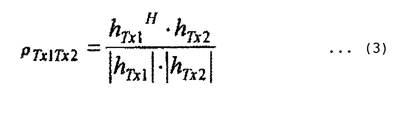
- The correlation value is calculated in this way. However, according to the present invention, since the access point includes a plurality of antennas, the system may calculates a combination of channel characteristics formed by the antennas. Or, it is also possible to select an appropriate number of antennas for the calculation of the channel characteristics. For each station, the total of the correlation values is calculated using expression (3) to select a combination for which the total is less than a threshold value (a combination with a lower correlation). The combination is designated as an SDMA group candidate. Any combination other than the combination for which the total exceeds a threshold value (a combination with a higher correlation) is selected. FIG. 11 shows an example in which the total of correlation values is calculated for each station in a system including, for example, an access point with four antennas, a
station STA # 1 with two antennas, astation STA # 2 with two antennas, and astation STA # 3 with two antennas. If the number of simultaneous connections is two, the correlation value for a combination ofSTA # 1 andSTA # 3 is 0.9. For a high correlation, it is not likely to obtain large channel capacity. Therefore, the SDMA group includingSTA # 1 andSTA # 3 is removed from the candidates. This resultantly reduces the number of calculation steps. - In a second mode of step S303, the system employs a method in which SDMA groups are beforehand estimated to reduce the number of calculation steps. The processing is executed by the wireless resource allocator 206 (specifically, the channel state information evaluator 206-a). As described above, in the operation using the SDMA, the higher the correlation between the channel matrices of the stations is, the more the channel capacity is. In the second mode, the system estimates a direction of each station, not the correlation. Stations apart from each other are categorized to belong to one and the same SDMA group. It is assumed now there exists an environment including, for example, an access point with four antennas, a
station STA # 1 with two antennas, astation STA # 2 with two antennas, and astation STA # 3 with two antennas. To estimate the direction of the station, there exist, for example, an MUSIC algorithm (a method of analyzing an eigen value of a covariance matrix of data received by a plurality of antennas) and a method of detecting the direction by turning 360° a beam having sharp directivity. By using such method of estimating the incoming direction, the system generates a table as shown in FIG. 12. It is not likely for stations, which exist in the vicinity of each other with respect to the direction, to gain large channel capacity. Therefore, SDMA group candidates including such stations are removed. In FIG. 12, since the access point is near thestation # 1 and thestation # 2 with respect to the direction, the SDMA group candidates including thestation # 1 and #2 are removed. This resultantly reduces the number of calculation steps. - In a third mode of step S303, the system employs a method to beforehand estimate SDMA groups to thereby reduce the number of calculation steps. The processing is executed by the wireless resource allocator 206 (specifically, the channel state information evaluator 206-a). In general, the channel capacity per station is larger in the communication conducted between a first unit and a second unit using the SDM technique in a one-to-one communication without using the SDMA technique than that in the communication conducted between a first unit and a plurality of units in a one-to-multi communication using the SDMA technique. Therefore, for each station, the system first confirms the channel state using, for example, the Received Signal Strength Indicator (RSSI). If the state is not appropriate, the calculation for the situation of the SDMA technique is not conducted for the station. The amount of calculation steps is resultantly reduced.
- It is also possible to select the SDMA group candidates by combining the first to third modes of step S303 with each other.
- Subsequently, for each station, the system calculates the channel capacity of the station when the SDMA technique is employed. The processing is executed by the wireless resource allocator 206 (specifically, the channel state information evaluator 206-a). Description will now be given of an example in which the MIMO-SDMA technique is employed for an access point with four antennas, a
station STA # 1 with two antennas, and astation STA # 2 with two antennas. In this situation, a reception signal R1 ofSTA # 1 and a reception signal R2 ofSTA # 2 are represented, using a transmission signal T1 toSTA # 1, a transmission signal T2 toSTA # 2, and channel matrices between the access point and the stations H11, H12, H21, and H22 as follows.
- When expression (4) is expanded, it is recognizable that in the reception signal R1 of
STA # 1, the transmission signal T2 to STA where #2 is superimposed as an interference wave in addition to a desired signal T1. Also, in the reception signal R2 ofSTA # 2, the transmission signal T1 toSTA # 1 is superimposed in addition to a desired signal T2. To suppress the interference, the access point beforehand adjusts the amplitude and phases of the signals. For example, in a null steering method, to set X to zero in advance, a null matrix is calculated using channel matrices. A result obtained by multiplying the null matrix thereto is transmitted to the system. The null steering method is described in the article, Andre Bourdoux, Nadia Khaled, "Joint Tx-Rx Optimisation for MIMO-SDMA Based on a Null-space Constraint", IEEE2002. pp. 171-172.
- As a result, mutually independent channels are formed between the access point and the stations. It is assumed to carry out an MIMO transmission, for example, an eigen-mode transmission (Eigenbeam Space Division Multiplex (E-SDM) transmission) using the mutually independent channels. Channel capacity C of E-SDM transmission is expressed as follows.


In expression (6), B indicates a signal bandwidth and γi is the SNR. Also, λi
indicates an eigen value obtained by conducting the Singular Value Decomposition (SVD) for a channel matrix as follows.
- Using the above method, the channel capacity is obtained for each station when the MIMO-SDMA technique is employed. Although the above method is available to obtain the channel capacity, it is also possible to estimate the channel capacity as a value estimated by approximation. In the embodiment, the evaluation of the channel state information, namely, the calculation of the channel capacity and calculation of weights are carried out by the channel state information evaluator 206-a. However, it is also possible to calculate the weights by the weight calculator 206-f as shown in FIG. 6. In expression (7), V and U are inputted via the
weight signal 15 to the weight module 203-b to be multiplied by each other in the combining module 203-a. For the weight calculation, there may also be employed a method using "Zero-Forcing (ZF)" or "Minimum Mean Square Error (MMSE)" in addition to "E-SDM". - In the description of the embodiment, the processing is executed in an order of steps S302, S303, and S304, namely, the listing, selection, and calculation of SDMA groups. However, the processing may also be executed in an order of steps S302, S304, and S303.
- In step S305, the system extracts information of requirement from each station or application. This processing is executed by the interface controller 205-a. The require information is measured in a predetermined method. For example, the require information is extracted by use of a predetermined protocol such as Hybrid Coordination Function Controlled Channel Access (HCCA) prescribed in the standard of IEEE802.1.1e. According to the HCCA, it is determined to conduct, before communication is started between a station and an access point, negotiation of communication quality therebetween. In a second method to measure the require information, the system measures information regarding a requirement described in a packet transmitted to the system. For example, the system extracts require information by analyzing a User's Priority header of IEEE802.1D.
- The require information in step S305 includes, throughput, priority, an application type, capacity of a buffer, delay, and jitter, in addition to the channel capacity.
- In step S306, the require information extracted in step S305 is converted into the index equal to that of the information processed in step S304. The processing is executed in the require information evaluator 206-b. The information of the wireless channel is converted into, for example, the channel capacity. If only the SNR is notified as the require information, the information is converted into the channel capacity by use of expression (6). The resultant value corresponds to a signal inputted from the require information evaluator 206-b to the optimizer 206-c. If the require information is associated with higher priority or a long delay, a large value may be outputted to the optimizer 206-c.
- The index value obtained by evaluating the channel state information or the require information is represented by a positive number. It is assumed that the larger the value is, the better the state of the channel is or the stronger the requirement is. However, there may be employed other indices. Also to reduce the amount of feedback information, it is possible to share, among the access point and the stations, tables each of which includes the information obtained by evaluating the channel state information and the channels such that table numbers respectively assigned thereto are communicated therebetween.
- In step S307, according to the channel state information and the require information, a plurality of SDMA group candidates are selected to calculate the time ratios for the selected SDMA groups. The processing receives as inputs thereto the SDMA groups and the tables (FIGS. 8 to 10) regarding the channel capacity for each station which are obtained by the channel state information evaluator 206-a, i.e., through processing in steps 302 and S303 and the channel capacity obtained in step S306 by the require information evaluator 206-b. The processing then determines the SDMA groups to be used and calculates the time ratio for each of the SDMA groups. There may be employed the Linear Programming (LP) as an example of the optimizing method to determine the SDMA groups to satisfy the communication capacity and to optimize the time ratios for the respective SDMA groups. The linear programming is a method of obtaining a maximum or minimum value of an objective function under conditions of constraint represented by inequalities of the first degree. Various algorithms have already been devised for the linear programming. The linear programming is implemented using conditions of constraint and the objective function. By changing the objective function, there is obtained a result corresponding to a target of the system while satisfying the conditions of constraint.


- In expression (8), αp is an unknown value indicating the ratio of time occupied by SDMA group #p, Xpq is a known value indicating the channel capacity of station #q belonging to SDMA group #p, TPq is the channel capacity required by station #q, m is the number of SDMA groups, and n is the number of stations. If there exists a solution (α1, α2, ...., αm) satisfying the expressions of constraint, all stations can satisfy the required channel capacity. Moreover, under the conditions of restriction, if a condition that an
objective function 

- If the system is expanded to include the uplink and downlink signals, there is obtained expression (11) as follows.


- In expression (11), αp is an unknown value indicating the ratio of time occupied by SDMA group #p for uplink transmission, βp is an unknown value indicating the ratio of time occupied by SDMA group #p for downlink transmission, Xpq is a known value indicating the channel capacity of station #q belonging to SDMA group #p for uplink transmission, Ypq is a known value indicating the channel capacity of station #q belonging to SDMA group #p for downlink transmission, TPXq is the channel capacity required by a station for uplink transmission, TPYq is the channel capacity required by a station for downlink transmission, m is the number of SDMA groups, and n is the number of stations.
- It is assumed that the system is expanded to include priority in addition to the uplink and downlink signals. The priority is categorized into two types, namely, a fixed quantity guarantee type (or real-time type such as voice, video, and streaming) and a relative guarantee type (or non-real-time type such as e-mail). The conditions of constraint are expressed as follows.

- In expression (12), αp is an unknown value indicating the ratio of time occupied by SDMA group #p for uplink transmission, βp is an unknown value indicating the ratio of time occupied by SDMA group #p for downlink transmission, Xpq is a known value indicating the channel capacity of station #q belonging to SDMA group #p for uplink transmission (fixed quantity guarantee type), Ypq is a known value indicating the channel capacity of station #q belonging to SDMA group #p for downlink transmission (fixed quantity guarantee type), X'pq is a known value indicating the channel capacity of station #q belonging to SDMA group #p for uplink transmission (relative guarantee type), Y'pq is a known value indicating the channel capacity of station #q belonging to SDMA group #p for downlink transmission (relative guarantee type), TPXq is the channel capacity required by a station for uplink transmission, TPYq is the channel capacity required by a station for downlink transmission, m is the number of SDMA groups, and n is the number of stations.
- Since the requirement of relative-guarantee-type stations is zero, the wireless resource can be allocated to the station of fixed quantity guarantee type with higher priority. Moreover, by adding a condition that an objective function

- In step S308, the system produce an allocation schedule by conducting a scheduling operation according to information regarding the wireless resource allocation for the respective stations determined by the optimizer 206-c, namely, the SDMA groups and the periods of time allocated to the respective SDMA groups. According to the schedule, the system controls the
wireless unit 202, thesignal processing unit 203, themodem controller 204, and thepacket controller 205. The result of wireless resource allocation represents the periods of time allocated to the respective SDMA groups. Therefore, it is only necessary to allocate time according to the ratio thus determined at an interval of time for the scheduling. The actual scheduling order is not restricted. An example of implementing the embodiment is HCCA in the standard of IEEE802.11e. According to HCCA, there is prescribed a protocol in which the access point controls operation of the stations in a centralized way by use of the polling control technique such that the access point and the stations perform wireless communication according to the scheduling of the access point. - FIG. 13 shows an example of wireless resource allocation according to the present invention (in a conceptual graph). In this graph in which the abscissa represents time, a period of time from a to b is allocated to wireless resources. The ordinate represents channel capacity, which varies between the SDMA groups.
- FIG. 14 shows a graph drawn after wireless resource allocation according to the present invention, the graph showing a relationship between the distance between an access point and a station and a probability of a case in which the required channel capacity is not secured. It is assumed that the system includes three stations.
Method 1 uses the MIMO technique, the quality of service is not taken into consideration, and a period of time obtained by equally dividing the channel estimation interval of time, 10 milliseconds (ms) is allocated to each station.Methods Method 2 does not take the quality of service into consideration. In the simulation, since the number of simultaneous connections of stations is two, three stations are classified into two groups including a group including two stations and a group including one station at random. Time is equally allocated to the SDMA groups. Inmethod 3, the quality of service is taken into consideration. From the SDMA groups, four groups are selected, the four groups being mutually different from each other. A judge step is conducted to determine whether or not the four groups include a group which secures the required channel capacity. However, time is equally allocated to the groups. In the method of the present invention, a judge step is conducted to determine whether or not conditions of restriction is satisfied, using the linear programming. The graph of FIG. 14 shows a relationship between the distance between an access point and a station of fixed quantity guarantee type and a probability of a case in which the required channel capacity is not secured. By comparing the MIMO technique (method 1) with the MIMO-SDMA technique (method 2) in which the quality of service is not taken into consideration, it is recognized that when the MIMO-SDMA technique (method 2) is used without taking the quality of service into consideration, the probability in which the required channel capacity cannot be secured for the distance of 15 meters (m) is deteriorated about ten times. This is because time is equally allocated to the SDMA groups. It is likely that the SDMA group including two stations cannot secure the required channel capacity. It is hence recognized that the characteristic is lower in the method using the SDMA technique than the conventional method depending on cases. Next, by comparingmethod 2 used without taking the quality of service into consideration withmethod 3 used by taking the quality of service into consideration, the probability is improved about 104 for the distance of 15 meters (m). It can be recognized that the method of the present invention is more superior in the characteristic to the above comparison methods. - FIG. 15 shows in a graph a relationship between the distance between an access point and a station of relative guarantee type and the total channel capacity of stations of relative guarantee type. It is assumed that the system includes stations of relative guarantee type in addition to three stations of fixed quantity guarantee type. In this situation, expression (13) in which the total channel capacity of the stations of relative guarantee type takes a maximum value is used as the objective function. It is assumed that the distance between the access point and each station of fixed quantity guarantee type is 15 meters and the channel capacity required by the station is 24 bits per second (bps). Among the stations, two stations request downlink transmission and one station requests uplink transmission. It is also assumed in this situation that, due to reversibility of the propagation path, one and the same channel capacity can be obtained for the downlink transmission and the uplink transmission. Since the number of stations of fixed quantity guarantee type becomes larger, the channel capacity is increased. This is because the probability of existence of the station capable of obtaining larger channel capacity becomes larger as the number of stations increases, because independent fading is provided for each station. It is recognizable that by use of the method of the present invention, the channel capacity of the stations of relative guarantee type can be secured while satisfying the requirements of stations of the fixed quantity guarantee type.
- The present invention is applicable to the wireless communication systems. The present invention is most efficiently applied to operation in which communication is conducted by allocating wireless resources using the SDMA technique.
- It should be further understood by those skilled in the art that although the foregoing description has been made on embodiments of the invention, the invention is not limited thereto and various changes and modifications may be made without departing from the spirit of the invention and the scope of the appended claims.
Claims (20)
- A wireless communication apparatus (101) for communicating with a plurality of stations (103) using a Space Division Multiple Access (SDMA), comprising:a channel state information collecting unit (202, 203) which collects channel state information of channels between the wireless communication apparatus and the plurality of stations;a wireless resource allocating unit (206) which generates a plurality of SDMA group candidates as candidates for SDMA groups formed by conducting the SDMA for the plurality of stations, estimates communication performance of each of the stations belonging to the SDMA group candidates by using the channel state information, selects an SDMA group from the plurality of SDMA groups according to the communication performance estimated for each station, and determines a period of time to be allocated to the selected SDMA group to thereby allocate wireless resources to the plurality of stations; anda signal processing unit (202, 203) which communicates with the plurality of stations using the wireless resources thus allocated.
- A wireless communication apparatus according to claim 1, further comprising a require information unit (205) which manages information of the communication performance required for each of the stations or information of communication performance required for an application provided to the station, wherein
the wireless resource allocating unit selects the SDMA groups and determines the allocation of a period of time to the SDMA group by use of the communication performance thus required. - A wireless communication apparatus according to claim 1 or claim 2, wherein the channel state information collecting unit collects, as the channel state information, a Signal to Noise power Ratio (SNR) or a Signal to Interference power Ratio (SIR).
- A wireless communication apparatus according to claim 2, wherein the communication performance thus required includes information of channel capacity required for the station or the application or information of delay allowed therefor.
- A wireless communication apparatus according to claim 1 or claim 2, wherein the wireless resource allocating unit determines the SDMA group candidates according to a correlation of the channel state information.
- A wireless communication apparatus according to claim 1 or claim 2, wherein the wireless resource allocating unit selects the SDMA groups and determines the allocation of a period of time to the SDMA group by conducting an optimizing calculation in which an evaluation index is minimization of a period of time required for data communication with the plurality of stations.
- A wireless communication apparatus according to claim 1 or claim 2, wherein the wireless resource allocating unit selects the SDMA groups and determines the allocation of a period of time to the SDMA group by conducting an optimizing calculation in which an evaluation index is maximization of a total of channel capacity for the plurality of stations.
- A wireless communication apparatus according to claim 1 or claim 2, wherein the wireless resource allocating unit selects the SDMA groups and determines the allocation of a period of time to the SDMA group by conducting an optimizing calculation in which an evaluation index is an operation to equally allocate the channel capacity to the respective stations.
- A wireless communication apparatus according to claim 2, wherein the wireless resource allocating unit selects the SDMA groups and determines the allocation of a period of time to the SDMA group by conducting an optimizing calculation in which if the communication performance thus required includes transmission data of absolute guarantee type and transmission data of relative guarantee type, an evaluation index is maximization of a total of channel capacity for communication of the transmission data of the relative guarantee type while satisfying a requirement of the communication performance for the transmission data of the absolute guarantee type.
- A wireless communication apparatus according to claim 2, wherein the wireless resource allocating unit selects the SDMA groups and determines the allocation of a period of time to the SDMA group by conducting an optimizing calculation in which if the communication performance thus required includes transmission data of absolute guarantee type and transmission data of relative guarantee type, an evaluation index is an operation to equally allocate channel capacity of the transmission data of the relative guarantee type to the respective stations while satisfying a requirement of the communication performance for the transmission data of the absolute guarantee type.
- A wireless resource allocation method for use in a wireless communication apparatus (101) for communicating with a plurality of stations (103) using a Space Division Multiple Access (SDMA), comprising:a first steps (S301) of collecting channel state information of channels between the wireless communication apparatus and the plurality of stations;a second step (S302) of generating a plurality of SDMA group candidates as candidates for SDMA groups formed by conducting the SDMA for the plurality of stations;a third step (S304, S307) of estimating communication performance of each of the stations belonging to the SDMA group candidates by using the channel state information, selecting an SDMA group from the plural SDMA groups according to the communication performance estimated for each of the stations, determining a period of time to be allocated to the SDMA group thus selected to thereby allocate wireless resources to the plurality of stations; anda fourth step of communicating with the plural stations using the allocated wireless resources.
- A wireless resource allocation method according to claim 11, further comprising a step of managing information of the communication performance required for each of the stations or information of communication performance required for an application provided to the station, wherein
the third step further comprises selecting the SDMA groups and determining the allocation of a period of time to the SDMA group by use of the communication performance thus required. - A wireless resource allocation method according to claim 12, further comprising a step of collecting, as the channel state information, a Signal to Noise power Ratio (SNR) or a Signal to Interference power Ratio (SIR).
- A wireless resource allocation method according to claim 12, wherein the communication performance thus required includes information of channel capacity required for the station or the application or information of delay allowed therefor.
- A wireless resource allocation method according to claim 12, wherein the second step further comprises determining the SDMA group candidates according to a correlation of the channel state information.
- A wireless resource allocation method according to claim 11, wherein the third step further comprises selecting the SDMA groups and determining the allocation of a period of time to the SDMA group through an optimizing calculation in which an evaluation index is minimization of a period of time required for data communication with the plurality of stations (FIG. 13).
- A wireless resource allocation method according to claim 11, the third step further comprises selecting the SDMA groups and determining the allocation of a period of time to the SDMA group through an optimizing calculation in which an evaluation index is maximization of a total of channel capacity for the plurality of stations (FIG. 13).
- A wireless resource allocation method according to claim 11, the third step further comprises selecting the SDMA groups and determining the allocation of a period of time to the SDMA group through an optimizing calculation in which an evaluation index is an operation to equally allocate the channel capacity to the respective stations.
- A wireless resource allocation method according to claim 12, wherein the third step further comprises selecting the SDMA groups and determining the allocation of a period of time to the SDMA group through an optimizing calculation in which if the communication performance thus required includes transmission data of absolute guarantee type and transmission data of relative guarantee type, an evaluation index is maximization of a total of channel capacity for communication of the transmission data of the relative guarantee type while satisfying a requirement of the communication performance for the transmission data of the absolute guarantee type (FIGS. 14 and 15).
- A wireless resource allocation method according to claim 12, the third step further comprises selecting the SDMA groups and determining the allocation of a period of time to the SDMA group through an optimizing calculation in which if the communication performance thus required includes transmission data of absolute guarantee type and transmission data of relative guarantee type, an evaluation index is an operation to equally allocate channel capacity of the transmission data of the relative guarantee type to the respective stations while satisfying a requirement of the communication performance for the transmission data of the absolute guarantee type (FIGS. 14 and 15).
Applications Claiming Priority (1)
| Application Number | Priority Date | Filing Date | Title |
|---|---|---|---|
| JP2006147575A JP4899637B2 (en) | 2006-05-29 | 2006-05-29 | Wireless communication system and wireless communication method |
Publications (2)
| Publication Number | Publication Date |
|---|---|
| EP1863304A1 true EP1863304A1 (en) | 2007-12-05 |
| EP1863304B1 EP1863304B1 (en) | 2016-02-24 |
Family
ID=38473998
Family Applications (1)
| Application Number | Title | Priority Date | Filing Date |
|---|---|---|---|
| EP07008981.8A Expired - Fee Related EP1863304B1 (en) | 2006-05-29 | 2007-05-03 | Systems and methods for wireless communication |
Country Status (4)
| Country | Link |
|---|---|
| US (1) | US8310995B2 (en) |
| EP (1) | EP1863304B1 (en) |
| JP (1) | JP4899637B2 (en) |
| CN (1) | CN101083516B (en) |
Cited By (7)
| Publication number | Priority date | Publication date | Assignee | Title |
|---|---|---|---|---|
| EP2245770A1 (en) * | 2008-01-23 | 2010-11-03 | LiveU Ltd. | Live uplink transmissions and broadcasting management system and method |
| US8542696B2 (en) | 2009-12-16 | 2013-09-24 | Intel Corporation | Device, system and method of simultaneously communicating with a group of wireless communication units |
| US8897185B2 (en) | 2009-12-17 | 2014-11-25 | Intel Corporation | Device, system and method of scheduling communications with a group of wireless communication units |
| US9338650B2 (en) | 2013-03-14 | 2016-05-10 | Liveu Ltd. | Apparatus for cooperating with a mobile device |
| US9369921B2 (en) | 2013-05-31 | 2016-06-14 | Liveu Ltd. | Network assisted bonding |
| US9379756B2 (en) | 2012-05-17 | 2016-06-28 | Liveu Ltd. | Multi-modem communication using virtual identity modules |
| US9980171B2 (en) | 2013-03-14 | 2018-05-22 | Liveu Ltd. | Apparatus for cooperating with a mobile device |
Families Citing this family (28)
| Publication number | Priority date | Publication date | Assignee | Title |
|---|---|---|---|---|
| JP2008060877A (en) * | 2006-08-31 | 2008-03-13 | Hitachi Ltd | Mimo radio data transmission system |
| US8249635B2 (en) * | 2007-06-18 | 2012-08-21 | Mitsubishi Electric Corporation | Communication method, wireless communication system, transmitter, and receiver |
| US20090059872A1 (en) * | 2007-08-31 | 2009-03-05 | Symbol Technologies, Inc. | Wireless dynamic rate adaptation algorithm |
| US7782755B2 (en) * | 2007-12-21 | 2010-08-24 | Motorola, Inc. | Method for uplink collaborative SDMA user pairing in WIMAX |
| US9178597B2 (en) | 2008-01-28 | 2015-11-03 | Broadcom Corporation | Method of updating transmission channel information based on eaves-dropping of beamformed signals |
| KR101381465B1 (en) * | 2008-02-20 | 2014-04-04 | 삼성전자주식회사 | Sdma communication system to feedback of a channel state information and therefor method |
| CN101534507B (en) * | 2008-03-12 | 2014-04-16 | 株式会社Ntt都科摩 | Physical resource distributing method and device |
| JP5193644B2 (en) * | 2008-03-26 | 2013-05-08 | 株式会社東芝 | Wireless communication apparatus, program and method |
| US8305885B2 (en) * | 2008-05-08 | 2012-11-06 | At&T Intellectual Property I, L.P. | Control of quality of service in overlapping basic service sets in wireless local area networks |
| TW200950410A (en) * | 2008-05-21 | 2009-12-01 | Realtek Semiconductor Corp | Channel utilizing method and system for wireless network |
| WO2010061768A1 (en) * | 2008-11-26 | 2010-06-03 | 京セラ株式会社 | Base station, method for arranging sub burst region in base station, method for determining terminal to be communicated with, and method for allocating downlink burst region |
| US8989106B2 (en) * | 2009-02-27 | 2015-03-24 | Qualcomm Incorporated | Methods and apparatuses for scheduling uplink request spatial division multiple access (RSDMA) messages in an SDMA capable wireless LAN |
| US8036098B2 (en) * | 2009-04-20 | 2011-10-11 | Intel Corporation | Wireless network and method for adaptive opportunistic clustering for interference alignment in wireless networks |
| JP5430306B2 (en) * | 2009-09-10 | 2014-02-26 | 京セラ株式会社 | Base station apparatus and base station apparatus communication control method |
| US8434336B2 (en) * | 2009-11-14 | 2013-05-07 | Qualcomm Incorporated | Method and apparatus for managing client initiated transmissions in multiple-user communication schemes |
| US8687546B2 (en) | 2009-12-28 | 2014-04-01 | Intel Corporation | Efficient uplink SDMA operation |
| US8693414B2 (en) | 2010-01-15 | 2014-04-08 | Ralink Technology Corp. | Multi-user transmission method, multiple input multiple output transmission system using the same, scheduling method and access point using the same for scheduling simultaneous transmission |
| WO2011094895A1 (en) * | 2010-02-05 | 2011-08-11 | Nokia Siemens Networks Oy | Method for scheduling user equipment in a radio communications system and apparatus thereof |
| KR101723274B1 (en) * | 2011-09-26 | 2017-04-18 | 엘지전자 주식회사 | Method and apparatus for allocating minimum guaranteed resource amount to access point in wireless access system |
| WO2013145593A1 (en) * | 2012-03-28 | 2013-10-03 | 京セラ株式会社 | Base station and communication control method |
| JP5729837B2 (en) * | 2012-09-26 | 2015-06-03 | 日本電信電話株式会社 | Base station apparatus, radio communication method, and radio communication system |
| JP5770699B2 (en) * | 2012-09-26 | 2015-08-26 | 日本電信電話株式会社 | Terminal apparatus, base station apparatus, radio communication method, and radio communication system |
| JP5895871B2 (en) * | 2013-02-22 | 2016-03-30 | 横河電機株式会社 | Management device, management method, and wireless communication system |
| FR3011704A1 (en) * | 2013-10-07 | 2015-04-10 | Orange | METHOD FOR IMPLEMENTING A COMMUNICATION SESSION BETWEEN A PLURALITY OF TERMINALS |
| CN106922013B (en) * | 2015-12-24 | 2020-04-21 | 华为技术有限公司 | Wireless access point of same-frequency-band double radio frequency modules and method for reducing signal interference |
| US10568126B2 (en) * | 2016-03-01 | 2020-02-18 | Huawei Technologies Co., Ltd. | Method and apparatus for distributed uplink data processing in a communication network with limited backhaul |
| FR3061623B1 (en) * | 2016-12-29 | 2019-05-31 | Avantix | METHOD AND DEVICE FOR OPTIMIZING THE COEXISTENCE OF PICO-RADIO NETWORKS |
| WO2020011714A1 (en) * | 2018-07-12 | 2020-01-16 | Sony Corporation | Controlling polarization division multiplex in mimo wireless communication |
Citations (3)
| Publication number | Priority date | Publication date | Assignee | Title |
|---|---|---|---|---|
| US20050147023A1 (en) * | 2003-12-30 | 2005-07-07 | Intel Corporation | Method and apparatus for implementing downlink SDMA in a wireless network |
| US6965774B1 (en) * | 2001-09-28 | 2005-11-15 | Arraycomm, Inc. | Channel assignments in a wireless communication system having spatial channels including enhancements in anticipation of new subscriber requests |
| US20050277444A1 (en) * | 2004-06-15 | 2005-12-15 | Samsung Electronics Co., Ltd. | Apparatus and method for downlink spatial division multiple access scheduling in a wireless network |
Family Cites Families (12)
| Publication number | Priority date | Publication date | Assignee | Title |
|---|---|---|---|---|
| US5926758A (en) * | 1996-08-26 | 1999-07-20 | Leo One Ip, L.L.C. | Radio frequency sharing methods for satellite systems |
| US5886988A (en) * | 1996-10-23 | 1999-03-23 | Arraycomm, Inc. | Channel assignment and call admission control for spatial division multiple access communication systems |
| GB0015512D0 (en) * | 2000-06-23 | 2000-08-16 | Univ Surrey | Channel allocation and assignment methods and systems |
| JP3967115B2 (en) * | 2001-11-22 | 2007-08-29 | 株式会社エヌ・ティ・ティ・ドコモ | Base station, radio resource control apparatus, terminal apparatus, communication system, and communication method |
| US7020110B2 (en) * | 2002-01-08 | 2006-03-28 | Qualcomm Incorporated | Resource allocation for MIMO-OFDM communication systems |
| JP4058326B2 (en) * | 2002-10-17 | 2008-03-05 | 株式会社エヌ・ティ・ティ・ドコモ | Wireless base station, control device, wireless communication system, and communication method |
| US7257088B2 (en) * | 2004-05-11 | 2007-08-14 | 3Com Corporation | SDMA system using MU-SIMO for the uplink and MU-MISO for the downlink |
| JP4583090B2 (en) * | 2004-06-29 | 2010-11-17 | 京セラ株式会社 | Communication apparatus and communication multiplexing method |
| US7961609B2 (en) * | 2004-07-20 | 2011-06-14 | Qualcomm Incorporated | Packet aware scheduler in wireless communication systems |
| US7620019B1 (en) * | 2004-08-27 | 2009-11-17 | Nortel Networks Limited | Space division multiple access scheduling |
| JP4447416B2 (en) * | 2004-09-22 | 2010-04-07 | 株式会社エヌ・ティ・ティ・ドコモ | Multiband mobile communication system and transmitter |
| US7512096B2 (en) * | 2004-11-24 | 2009-03-31 | Alcatel-Lucent Usa Inc. | Communicating data between an access point and multiple wireless devices over a link |
-
2006
- 2006-05-29 JP JP2006147575A patent/JP4899637B2/en not_active Expired - Fee Related
-
2007
- 2007-02-28 CN CN2007100843708A patent/CN101083516B/en not_active Expired - Fee Related
- 2007-05-02 US US11/797,321 patent/US8310995B2/en not_active Expired - Fee Related
- 2007-05-03 EP EP07008981.8A patent/EP1863304B1/en not_active Expired - Fee Related
Patent Citations (3)
| Publication number | Priority date | Publication date | Assignee | Title |
|---|---|---|---|---|
| US6965774B1 (en) * | 2001-09-28 | 2005-11-15 | Arraycomm, Inc. | Channel assignments in a wireless communication system having spatial channels including enhancements in anticipation of new subscriber requests |
| US20050147023A1 (en) * | 2003-12-30 | 2005-07-07 | Intel Corporation | Method and apparatus for implementing downlink SDMA in a wireless network |
| US20050277444A1 (en) * | 2004-06-15 | 2005-12-15 | Samsung Electronics Co., Ltd. | Apparatus and method for downlink spatial division multiple access scheduling in a wireless network |
Cited By (17)
| Publication number | Priority date | Publication date | Assignee | Title |
|---|---|---|---|---|
| US9712267B2 (en) | 2008-01-23 | 2017-07-18 | Liveu Ltd. | Live uplink transmissions and broadcasting management system and method |
| US10601533B2 (en) | 2008-01-23 | 2020-03-24 | Liveu Ltd. | Live uplink transmissions and broadcasting management system and method |
| US9154247B2 (en) | 2008-01-23 | 2015-10-06 | Liveu Ltd. | Live uplink transmissions and broadcasting management system and method |
| US10153854B2 (en) | 2008-01-23 | 2018-12-11 | Liveu Ltd. | Live uplink transmissions and broadcasting management system and method |
| EP2245770A1 (en) * | 2008-01-23 | 2010-11-03 | LiveU Ltd. | Live uplink transmissions and broadcasting management system and method |
| US8542696B2 (en) | 2009-12-16 | 2013-09-24 | Intel Corporation | Device, system and method of simultaneously communicating with a group of wireless communication units |
| US9060368B2 (en) | 2009-12-16 | 2015-06-16 | Intel Corporation | Article of simultaneously communicating with a group of wireless communication units |
| US9877223B2 (en) | 2009-12-16 | 2018-01-23 | Intel Corporation | Apparatus and article of simultaneously transmitting to a group of wireless communication stations |
| US10039123B2 (en) | 2009-12-17 | 2018-07-31 | Intel Corporation | Device, system and method of scheduling communications with a group of wireless communication units |
| US9320054B2 (en) | 2009-12-17 | 2016-04-19 | Intel Corporation | Device, system and method of scheduling communications with a group of wireless communication units |
| US8897185B2 (en) | 2009-12-17 | 2014-11-25 | Intel Corporation | Device, system and method of scheduling communications with a group of wireless communication units |
| US9379756B2 (en) | 2012-05-17 | 2016-06-28 | Liveu Ltd. | Multi-modem communication using virtual identity modules |
| US9980171B2 (en) | 2013-03-14 | 2018-05-22 | Liveu Ltd. | Apparatus for cooperating with a mobile device |
| US9338650B2 (en) | 2013-03-14 | 2016-05-10 | Liveu Ltd. | Apparatus for cooperating with a mobile device |
| US10667166B2 (en) | 2013-03-14 | 2020-05-26 | Liveu Ltd. | Apparatus for cooperating with a mobile device |
| US9369921B2 (en) | 2013-05-31 | 2016-06-14 | Liveu Ltd. | Network assisted bonding |
| US10206143B2 (en) | 2013-05-31 | 2019-02-12 | Liveu Ltd. | Network assisted bonding |
Also Published As
| Publication number | Publication date |
|---|---|
| US20070274256A1 (en) | 2007-11-29 |
| JP4899637B2 (en) | 2012-03-21 |
| EP1863304B1 (en) | 2016-02-24 |
| CN101083516B (en) | 2012-10-24 |
| CN101083516A (en) | 2007-12-05 |
| US8310995B2 (en) | 2012-11-13 |
| JP2007318576A (en) | 2007-12-06 |
Similar Documents
| Publication | Publication Date | Title |
|---|---|---|
| EP1863304B1 (en) | Systems and methods for wireless communication | |
| US10966203B2 (en) | Transmission apparatus and transmission method using a plurality of divided frequency bands in a communication band | |
| KR101507088B1 (en) | Aparatus and method for uplink baemforming and space-division multiple access in multi-input multi-output wireless communication systems | |
| EP2227869B1 (en) | Method for reducing inter-cell interference | |
| US8009578B2 (en) | Wireless base station device, terminal, and wireless communication method | |
| US9276652B2 (en) | Wireless communication system and wireless communication method | |
| JP5957000B2 (en) | System and method for coordinating transmissions in a distributed wireless system through user clustering | |
| US7702353B2 (en) | Transmit power allocation in a distributed MIMO system | |
| KR101103482B1 (en) | A measurement method for spatial scheduling | |
| US8295213B2 (en) | Method, system and apparatus for uplink space transmission of TDD system | |
| EP1505741A2 (en) | Method and apparatus for scheduling multiple users in a mobile communication system using multiple transmit/receive antennas | |
| US20070258392A1 (en) | Method and Apparatus in a Mimo Based Communication System | |
| EP2564648B1 (en) | Method and system for scheduling radio links by means of spatial reuse | |
| US20100103900A1 (en) | Beamforming method and device | |
| US20090196203A1 (en) | Wireless communication system and communication control method | |
| WO2006080352A1 (en) | Radio base station device and terminal device | |
| KR20060054417A (en) | Radio transmission control method, radio receiver apparatus, and radio transmitter apparatus | |
| US7940690B2 (en) | Apparatus and method for determining transmission mode in wireless communication system | |
| JP4402127B2 (en) | Transmission method and apparatus for spatial multiplexing transmission | |
| Hammarwall et al. | Utilizing the spatial information provided by channel norm feedback in SDMA systems | |
| WO2011046825A1 (en) | An adaptive beam-forming and space-frequency block coding transmission scheme for mimo-ofdma systems | |
| US20070098123A1 (en) | Method for controlling the transfer of signals representative of au group of data | |
| CN111800217A (en) | Full-duplex cognitive multi-input multi-output relay cooperation method under non-ideal channel state | |
| KR101298136B1 (en) | Apparatus and method for beamforming in multiple antenna systems | |
| US11483038B1 (en) | Systems and methods for user grouping within a wireless local area network (WLAN) |
Legal Events
| Date | Code | Title | Description |
|---|---|---|---|
| PUAI | Public reference made under article 153(3) epc to a published international application that has entered the european phase |
Free format text: ORIGINAL CODE: 0009012 |
|
| AK | Designated contracting states |
Kind code of ref document: A1 Designated state(s): AT BE BG CH CY CZ DE DK EE ES FI FR GB GR HU IE IS IT LI LT LU LV MC MT NL PL PT RO SE SI SK TR |
|
| AX | Request for extension of the european patent |
Extension state: AL BA HR MK YU |
|
| 17P | Request for examination filed |
Effective date: 20080208 |
|
| 17Q | First examination report despatched |
Effective date: 20080428 |
|
| AKX | Designation fees paid |
Designated state(s): DE FR GB |
|
| REG | Reference to a national code |
Ref document number: 602007044945 Country of ref document: DE Ref country code: DE Ref legal event code: R079 Free format text: PREVIOUS MAIN CLASS: H04Q0007360000 Ipc: H04W0072080000 |
|
| RIC1 | Information provided on ipc code assigned before grant |
Ipc: H04W 72/08 20090101AFI20110228BHEP |
|
| GRAP | Despatch of communication of intention to grant a patent |
Free format text: ORIGINAL CODE: EPIDOSNIGR1 |
|
| INTG | Intention to grant announced |
Effective date: 20150709 |
|
| RIN1 | Information on inventor provided before grant (corrected) |
Inventor name: MURAI, SHINJI Inventor name: SHIDA, MASAAKI Inventor name: YANO, TAKASHI Inventor name: HAYASE, SHIGENORI Inventor name: ISHIFUJI, TOMOAKI |
|
| GRAS | Grant fee paid |
Free format text: ORIGINAL CODE: EPIDOSNIGR3 |
|
| GRAA | (expected) grant |
Free format text: ORIGINAL CODE: 0009210 |
|
| INTG | Intention to grant announced |
Effective date: 20151218 |
|
| AK | Designated contracting states |
Kind code of ref document: B1 Designated state(s): DE FR GB |
|
| REG | Reference to a national code |
Ref country code: GB Ref legal event code: FG4D |
|
| REG | Reference to a national code |
Ref country code: DE Ref legal event code: R096 Ref document number: 602007044945 Country of ref document: DE |
|
| REG | Reference to a national code |
Ref country code: FR Ref legal event code: PLFP Year of fee payment: 10 |
|
| REG | Reference to a national code |
Ref country code: DE Ref legal event code: R097 Ref document number: 602007044945 Country of ref document: DE |
|
| PLBE | No opposition filed within time limit |
Free format text: ORIGINAL CODE: 0009261 |
|
| STAA | Information on the status of an ep patent application or granted ep patent |
Free format text: STATUS: NO OPPOSITION FILED WITHIN TIME LIMIT |
|
| 26N | No opposition filed |
Effective date: 20161125 |
|
| REG | Reference to a national code |
Ref country code: FR Ref legal event code: PLFP Year of fee payment: 11 |
|
| REG | Reference to a national code |
Ref country code: FR Ref legal event code: PLFP Year of fee payment: 12 |
|
| PGFP | Annual fee paid to national office [announced via postgrant information from national office to epo] |
Ref country code: GB Payment date: 20180329 Year of fee payment: 12 |
|
| PGFP | Annual fee paid to national office [announced via postgrant information from national office to epo] |
Ref country code: DE Payment date: 20180417 Year of fee payment: 12 |
|
| PGFP | Annual fee paid to national office [announced via postgrant information from national office to epo] |
Ref country code: FR Payment date: 20180412 Year of fee payment: 12 |
|
| REG | Reference to a national code |
Ref country code: DE Ref legal event code: R119 Ref document number: 602007044945 Country of ref document: DE |
|
| GBPC | Gb: european patent ceased through non-payment of renewal fee |
Effective date: 20190503 |
|
| PG25 | Lapsed in a contracting state [announced via postgrant information from national office to epo] |
Ref country code: DE Free format text: LAPSE BECAUSE OF NON-PAYMENT OF DUE FEES Effective date: 20191203 Ref country code: GB Free format text: LAPSE BECAUSE OF NON-PAYMENT OF DUE FEES Effective date: 20190503 |
|
| PG25 | Lapsed in a contracting state [announced via postgrant information from national office to epo] |
Ref country code: FR Free format text: LAPSE BECAUSE OF NON-PAYMENT OF DUE FEES Effective date: 20190531 |