US20030190897A1 - Method for selecting switched orthogonal beams for downlink diversity transmission - Google Patents
Method for selecting switched orthogonal beams for downlink diversity transmission Download PDFInfo
- Publication number
- US20030190897A1 US20030190897A1 US10/116,240 US11624002A US2003190897A1 US 20030190897 A1 US20030190897 A1 US 20030190897A1 US 11624002 A US11624002 A US 11624002A US 2003190897 A1 US2003190897 A1 US 2003190897A1
- Authority
- US
- United States
- Prior art keywords
- beams
- pair
- selecting
- orthogonal
- determining
- Prior art date
- Legal status (The legal status is an assumption and is not a legal conclusion. Google has not performed a legal analysis and makes no representation as to the accuracy of the status listed.)
- Granted
Links
Images


Classifications
-
- H—ELECTRICITY
- H04—ELECTRIC COMMUNICATION TECHNIQUE
- H04B—TRANSMISSION
- H04B7/00—Radio transmission systems, i.e. using radiation field
- H04B7/02—Diversity systems; Multi-antenna system, i.e. transmission or reception using multiple antennas
- H04B7/04—Diversity systems; Multi-antenna system, i.e. transmission or reception using multiple antennas using two or more spaced independent antennas
- H04B7/06—Diversity systems; Multi-antenna system, i.e. transmission or reception using multiple antennas using two or more spaced independent antennas at the transmitting station
- H04B7/0686—Hybrid systems, i.e. switching and simultaneous transmission
- H04B7/0695—Hybrid systems, i.e. switching and simultaneous transmission using beam selection
-
- H—ELECTRICITY
- H04—ELECTRIC COMMUNICATION TECHNIQUE
- H04B—TRANSMISSION
- H04B7/00—Radio transmission systems, i.e. using radiation field
- H04B7/02—Diversity systems; Multi-antenna system, i.e. transmission or reception using multiple antennas
- H04B7/04—Diversity systems; Multi-antenna system, i.e. transmission or reception using multiple antennas using two or more spaced independent antennas
- H04B7/0408—Diversity systems; Multi-antenna system, i.e. transmission or reception using multiple antennas using two or more spaced independent antennas using two or more beams, i.e. beam diversity
-
- H—ELECTRICITY
- H04—ELECTRIC COMMUNICATION TECHNIQUE
- H04B—TRANSMISSION
- H04B7/00—Radio transmission systems, i.e. using radiation field
- H04B7/02—Diversity systems; Multi-antenna system, i.e. transmission or reception using multiple antennas
- H04B7/04—Diversity systems; Multi-antenna system, i.e. transmission or reception using multiple antennas using two or more spaced independent antennas
- H04B7/06—Diversity systems; Multi-antenna system, i.e. transmission or reception using multiple antennas using two or more spaced independent antennas at the transmitting station
- H04B7/0613—Diversity systems; Multi-antenna system, i.e. transmission or reception using multiple antennas using two or more spaced independent antennas at the transmitting station using simultaneous transmission
- H04B7/0615—Diversity systems; Multi-antenna system, i.e. transmission or reception using multiple antennas using two or more spaced independent antennas at the transmitting station using simultaneous transmission of weighted versions of same signal
- H04B7/0617—Diversity systems; Multi-antenna system, i.e. transmission or reception using multiple antennas using two or more spaced independent antennas at the transmitting station using simultaneous transmission of weighted versions of same signal for beam forming
-
- H—ELECTRICITY
- H04—ELECTRIC COMMUNICATION TECHNIQUE
- H04B—TRANSMISSION
- H04B7/00—Radio transmission systems, i.e. using radiation field
- H04B7/02—Diversity systems; Multi-antenna system, i.e. transmission or reception using multiple antennas
- H04B7/04—Diversity systems; Multi-antenna system, i.e. transmission or reception using multiple antennas using two or more spaced independent antennas
- H04B7/06—Diversity systems; Multi-antenna system, i.e. transmission or reception using multiple antennas using two or more spaced independent antennas at the transmitting station
- H04B7/0613—Diversity systems; Multi-antenna system, i.e. transmission or reception using multiple antennas using two or more spaced independent antennas at the transmitting station using simultaneous transmission
- H04B7/0667—Diversity systems; Multi-antenna system, i.e. transmission or reception using multiple antennas using two or more spaced independent antennas at the transmitting station using simultaneous transmission of delayed versions of same signal
- H04B7/0669—Diversity systems; Multi-antenna system, i.e. transmission or reception using multiple antennas using two or more spaced independent antennas at the transmitting station using simultaneous transmission of delayed versions of same signal using different channel coding between antennas
Definitions
- the invention relates in general to wireless communication systems. More particularly, it relates to a system for improving the downlink transmission performance of wireless communication systems.
- Wireless communications may suffer from four major impairments, namely path loss, multipath fading, inter-symbol interference and co-channel interference.
- Adaptive antenna systems may be used to suppress the effects of such impairments to improve the performance of wireless communication systems.
- diversity antenna systems multiple low-correlation or independent fading channels are utilised in order to compensate multipath fading, thus achieving diversity gain.
- Beamforming antenna systems achieve beamforming gain by applying spatial directivity, thus limitedly compensating for path loss and suppressing co-channel interference.
- antenna spacing is usually required to be sufficiently large, for example 10 ⁇ , in order to achieve low-correlation or independent fading channels. This is especially true for small angular spread environments.
- a beamforming antenna system need to achieve spatial directivity, so signals received at and/or transmitted from all beamforming antennas must be correlated. This means that for a beamforming antenna system, antenna spacing is usually small, for example half wavelength for a uniform linear array (ULA).
- ULA uniform linear array
- a classical approach to achieving antenna diversity is to use multiple antennas at the receiver and perform combining or selection to improve the quality of the received signal.
- the major problems faced with using the receiving antenna diversity or diversity reception approach in the downlink of wireless communication systems relate to constraints in cost, size and power consumption of the receiver. For apparent reasons, features such as small size, lightweight and low cost are paramount considerations in designing wireless communications receivers.
- RF radio frequency
- STTC space-time trellis coding
- the space-time trellis codes proposed provide the best possible trade-off between constellation size, data rate, diversity advantage, and trellis complexity.
- the decoding complexity of the STTC technique increases exponentially as a function of both diversity level and transmission rate.
- S. M. Alamouti proposes a scheme for transmission using two antennas in “A simple diversity transmission technique for wireless communications”, IEEE Journal of Selected Areas in Communications, Vol. 16, No.8, pp.1451-1458, October 1998. This involves a maximum likelihood detection scheme based only on linear processing at the receiver.
- STBC space-time block coding
- FIG. 1 is a block diagram of a wireless communication system for illustrating Alamouti's proposed diversity scheme using two transmitting antennas 102 equipped at a base station (BS) 104 for achieving diversity transmission.
- a signal s(n) to be transmitted is first coded in a space-time block coding module 106 in the base station 104 which has one input port 108 and two output ports 110 .
- the input port 108 accepts the transmitted sequence, s(0), s(1), . . .
- n is an even integer and ‘*’ denotes a complex conjugate operation.
- ⁇ 1 and ⁇ 2 are the respective channel coefficients 116 from the two transmitting antennas 102 to the receiving antenna 112 , respectively, and v(n) is the additive white Gaussian noise (AWGN).
- AWGN additive white Gaussian noise
- channel coefficients 116 may be estimated via equation (3) using training symbols, while equation (4) may be used for signal estimation/detection.
- channel coefficient estimation and signal detection involve very simple linear operations.
- the scheme achieves the same order of diversity gain as diversity reception techniques using a maximum ratio combining (MRC) approach, although the scheme suffers from a 3 dB performance loss.
- MRC maximum ratio combining
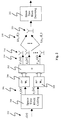
- FIG. 2 shows a system employing the STBC technique, which combines beamforming technique with diversity transmission.
- a signal to be transmitted, s(n) is first provided to an input 202 of a space-time block encoder 204 and coded by it yielding two branch outputs 206 as s 1 (n) and s 2 (n).
- the output signals are then passed into two transmit beamformers w 1 208 and w 2 210 for beamforming processing, and passed on to a signal combiner 212 which performs a simple summing function of the two beamforming processed inputs to produce a vector signal x(n) 214 for transmission through multiple antennas 216 .
- a( ⁇ l ) is the downlink steering vector at DOA ⁇ l .
- transmission beamforming weights may be estimated by maximizing the cost function:
- the optimal transmission beamforming weight vectors are Eigenvectors corresponding to the two largest Eigenvalues of the downlink channel covariance matrix:
- this scheme requires only up to second order statistics of fading channel.
- beamforming weights are guaranteed to be optimal for Rayleigh/Rice fading channel only.
- the aforementioned schemes for systems employing either the STTC or STBC technique achieve diversity gain and optimal beamforming gain via combining the space-time coding techniques with the adaptive beamforming technique.
- the optimal beamforming weights may be obtained through either SVD or Eigen-decomposition.
- theoretical performance benefits achieved by the adaptive systems may be offset by the cost and complexities encountered in implementation.
- received complex envelopes of signals vary rapidly due to fading.
- the adaptive beamformer must therefore “track” the change in the fading envelope so that beamforming weights always meet the optimality requirements. If the tracking performance using the adaptive algorithm is not sufficient, beamforming performances may degrade.
- the switched beam antenna system consists of multiple narrow beams, of which the beam considered best or has the strongest received power is used to serve a desired mobile terminal as it is moved through the coverage of a base station.
- the switched beam antenna system is more economical to implement, requiring only a static beamforming network, RF switch and control.
- Commercial deployments of switched beam antenna systems have demonstrated significant performance improvements over systems without multiple antennas. Nevertheless, the performance of the switched beam antenna system is considered by those skilled in the art to be inferior to that of the adaptive antenna system.
- a method for selecting two beams in a switched beam antenna system for providing downlink communications in a downlink channel the switched beam antenna system providing uplink reception and downlink transmission.
- the method comprises the steps of selecting a pair of beams based on the uplink reception of the switched beam antenna system, and determining from the pair of beams a corresponding pair of orthogonal beams.
- the method further comprises the step of providing the pair of orthogonal beams as a pair of transmit beams for the downlink transmission of the switched beam antenna system.
- a switched beam antenna system for selecting two beams for providing downlink communications in a downlink channel, the switched beam antenna system further providing uplink reception and downlink transmission.
- the system comprises means for selecting a pair of beams based on the uplink reception of the switched beam antenna system, and means for determining from the pair of beams a corresponding pair of orthogonal beams.
- the system further comprises means for providing the pair of orthogonal beams as a pair of transmit beams for the downlink transmission of the switched beam antenna system.
- FIG. 1 is a block diagram of a conventional downlink transmission system using the STBC technique
- FIG. 2 is a block diagram of a conventional downlink transmission system combining an adaptive antenna system with the STBC technique
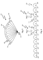
- FIG. 3 illustrates a switched beam antenna system with twelve beams per sector
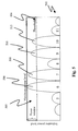
- FIG. 4 illustrates the twelve beams shown in FIG. 3 being accentuated to show a twelve-beam pattern
- FIG. 5 shows a beam pattern depicting measured powers of two pairs of beams corresponding to incoming paths of a system according to an embodiment of the invention combining the switched beam antenna system of FIG. 3 with the STBC technique;
- FIG. 6 is a flowchart of operations in a system according to an embodiment of the invention for selecting a pair of switched orthogonal beams using the switched beam antenna system of FIG. 3;
- FIGS. 7 a to 7 c are tabulated simulation results illustrating downlink BER performance vs. DOA for comparing the performance of the system of FIG. 5 with other systems;
- FIGS. 8 a to 8 c are tabulated simulation results illustrating downlink BER performance vs. transmit power (SNR) for comparing the performance of the system of FIG. 5 with other systems;
- FIG. 9 is a block diagram of a conventional multiple input-multiple output (MIMO) system.
- FIG. 10 is a block diagram of another system according to an embodiment of the invention combining the switched beam antenna system of FIG. 3 with the MIMO technique.
- a system according to an embodiment of the invention is disclosed hereinafter to address the need for a system that provides the performance of an adaptive antenna system while possessing the implementation simplicity of a switched beam system for achieving diversity gain and beamforming gain simultaneously
- Such a system involves a practical, inexpensive, and robust downlink transmission scheme for achieving both diversity and beamforming gain based on some simple uplink measurements.
- the system approximates the maximum beamforming gain and achieves full diversity transmission as well by combining the STBC technique with a switched beam antenna system.
- the switched beam antenna system preferably has the same simple physical structure as that employed for uplink in a base station.
- the system involves a downlink diversity transmission scheme to combat fading effect for wireless communication systems where multiple antennas are employed in base stations while only a single antenna is employed in mobile terminals.
- a number of advantages are associated with such a system, which are described hereinafter.
- the system includes a low cost switched beam system, and thus is simple to implement and cost effective. And in such a system, diversity transmission is fully obtained. At the same time, the beamforming gain is maximized to an approximating optimum value that is conventionally achieved by complex adaptive antenna systems. Furthermore, the scheme used in the system is applicable to frequency-selective fading channel when employed in CDMA and OFDM systems. The scheme is also applicable to either TDD systems or FDD systems. Additionally, the system by achieving combined beamforming and diversity transmission provides high spectrum efficiency, yet consumes less transmission power. Lastly, since a mobile terminal is usually limited by physical size and battery power, the system allows complicated processing to be performed at a base station, rather at the mobile terminal, thus reducing the mobile terminal complexity.
- the architecture of the system is similar to the conventional system shown in FIG. 2, with only one important distinction relating to two transmit beamformers w 1 208 and w 2 210 .
- the beamforming weights used in the beamformers w 1 208 and w 2 210 are computed using processes, methods, and techniques described hereinafter.
- FIG. 3 illustrates a switched beam antenna system 300 which is used in the system, with twelve beams 302 in each 120° sector, each beam 304 having a 10° width.
- the objective is to select one best beam at a time for reception or transmission, respectively.
- a simple and efficient method to achieve this is to calculate the power level at the uplink receiver output in the system for each beam and select the beam with the highest output power for uplink reception or downlink transmission.
- the conventional switched beam system is combined with the STBC technique for providing downlink transmission, two beams are needed, and correspondingly two sets of beamforming weights, at a time.
- a direct extension from the single strongest beam technique such a system has to select two strongest beams in terms of receiving power.
- the inferior performance of the “two strongest” beams technique is mainly due to the non-orthogonality, instead of lower accuracy relating to directivity to the desired mobile terminal, of the two strongest beams as opposed to adaptive beams.
- the first and second strongest beams are usually either adjacent, for example first and second beams 306 and 308 shown in FIG. 1, or separated by only one beam, thereby providing two highly correlated virtual fading channels, ⁇ 1 (t) and ⁇ 2 (t).
- the diversity gain which is more essential for system performance in a fading environment, is not fully obtained.
- the system therefore has to generate plenty of pairs of orthogonal beams for selection or switching.
- the selected orthogonal beams should always direct to the signal path where most of the signal power lies.
- the Eigen-decomposition method is preferably applied in the system to produce orthogonal beams and corresponding beamforming weights, because the system not only produces orthogonal beams but also control the directivity of the beams produced.
- two switched beams at directions of most signal power concentrated may be identified using processes, methods, and techniques described hereinafter.
- Eigen-decomposition is applied to generate orthogonal beams while keeping the directivity of the conventional beams. The system generates each pair of orthogonal beams based on two or more switched beams.
- the main beam directions are ⁇ i and ⁇ j , respectively.
- the covariance matrix of the corresponding downlink channels may be appropriately approximated by:
- a pair of orthogonal beams corresponding to switched beams i and j may be found as Eigenvectors of ⁇ circumflex over (R) ⁇ corresponding to two largest Eigenvalues. In this way, a mapping from any two switched beams i and j (i ⁇ j) amongst all possible combination of two switched beams to the corresponding pair of orthogonal beams may be established.
- mapping can be established similarly from all N switched beams to corresponding pairs of orthogonal beams. Since this mapping employs Eigen-decomposition is fixed once the communication system is established, the mapping procedure preferably using off-line processing, and therefore does not contribute to the complexity of the system. This is an advantage over adaptive antenna systems in which Eigen-decomposition is applied on-line.
- the two strongest beams for each incoming path are adjacent, and therefore in this case, either the pair comprising sixth 408 and seventh 410 beams or the pair comprising ninth 412 and tenth 414 beams provide the strongest beams.
- the method also includes an optimal switched beams selection technique described in greater detail hereinafter.
- the method provides for the process of selecting the best two beams which ideally cover incoming paths with more power and less correlation with respect to each other.
- the method preferably uses a power window threshold 504 of a power window 505 shown in FIG. 5, in which a beam pattern 502 depicts measured powers of the two pairs of beams corresponding to the incoming paths.
- the power window threshold 504 takes reference from the maximum power measured at the output of each of the beams, in this case the sixth beam 506 . All the beams with output power within the employed power window 505 are selected in this process, in this case the sixth 506 , seventh 508 , ninth 510 , and tenth 512 beams.
- R is the downlink channel covariance matrix which may be estimated from uplink measurements.
- W i,j [w i w j ]
- R is the downlink channel covariance matrix which may be estimated from uplink measurements.
- R is the same as uplink channel covariance matrix and may be obtained using a simple averaging scheme:
- the downlink channel covariance matrix may be obtained via frequency calibration processing to uplink channel covariance matrix R u as described in Annex A.
- the diagonal elements in F i,j contribute to transmit power of two virtual paths while non-orthogonal elements contribute to the correlation between the two virtual paths. Taking into consideration the maximization of transmit power and minimization of cross correlation,
- [0062] may be used as a cost function to choose the beam pair having the maximum value of ⁇ among the selected beam pairs.
- Other cost functions may also be used for choosing the beam pair.
- the beam pair may be chosen based on maximum or minimum values of the cost function. For the case illustrated in FIG. 5, the system through the beam selection process selects one from the pair comprising the sixth 506 and seventh 508 beams and another from the pair comprising the ninth 510 and tenth 504 beams.
- a step 602 for setting up the antenna system a set of mappings from any two switched beams to the corresponding orthogonal beam pair is prepared and stored in the system memory.
- the orthogonal beams are calculated as Eigenvectors corresponding to two largest Eigenvalues of matrix ⁇ circumflex over (R) ⁇ in (14). This step is performed off-line.
- a step 604 all the beams with output power of uplink within power window threshold are selected. Then in a further step 606 , a check for the number of selected beams is performed. If the number of selected beams is two, a next step 608 is skipped and the system proceeds to a step 610 .
- the cost function in (17) using (15) and (16) is calculated for all combinations of beam pairs among the selected beams.
- the two beams with a maximum value of the cost function are identified.
- the orthogonal beam pair is then mapped from the two identified beams in the step 610 as transmitting beams w 1 and w 2 using the mapping information stored in the system in the step 602 .
- the switched orthogonal beam selection method in the system is derived herein in relation to frequency non-selective fading channels, it is also applicable to frequency selective channels where Code Division Multiplex Access (CDMA) systems or Orthogonal Frequency Division Multiplex (OFDM) systems are employed.
- CDMA Code Division Multiplex Access
- OFDM Orthogonal Frequency Division Multiplex
- BER bit error rate
- a base station is equipped with 6-element and half-wavelength spaced ULA antenna while a mobile terminal has only single antenna. Twelve switched beams per sector are adopted for both uplink reception and downlink transmission.
- the communications channel is assumed Rayleigh fading with normalized Doppler shift 0.01 (maximum Doppler shift ⁇ sample time interval), and the channel is second order with angular spread set to 10°, 30°, and 60° representing small, moderate, and large angular spreads respectively.
- DOA direction of arrival
- FIGS. 7 a to 7 c and FIGS. 8 a to 8 c The downlink BER performance vs. DOA and transmit power (SNR) is illustrated in FIGS. 7 a to 7 c and FIGS. 8 a to 8 c , respectively.
- performances of three alternative systems are also included. These include a system combining the STBC technique with adaptive beamforming scheme (system A), a system combining the STBC technique with a scheme using two strongest conventional switched beams (system B), and a system combining the STBC technique with a scheme using orthogonal beam pairs corresponding to the two strongest beams (system C).
- system D The system described hereinbefore is known as system D.
- the system may approximate the maximum beamforming gain and achieve diversity transmission as well by combining the STTC technique with a switched beam antenna system using the switched orthogonal beam selection method described hereinbefore.
- the system may use a Multiple Input Multiple Output (MIMO) wireless communication system in combination with a switched beam antenna system using the switched orthogonal beam selection method for achieving beamforming gain as well as diversity gain.
- MIMO Multiple Input Multiple Output
- FIG. 9 a block diagram in FIG. 9 is referenced hereinafter which shows two transmitting antennas 902 in a base station 904 and two receiving antennas 906 in a mobile terminal 908 .
- Such an MIMO system is known as a two input-two output MIMO system in which a serial sequence of original signals s(n), s(n+1) . . .
- the MIMO system is designed to achieve higher data throughput or transmission data rate and greater spectrum efficiency for wireless communication systems. From the architecture, it is clear that in the MIMO system, the transmission data rate is double compared to a system employing the STBC or STTC technique.
- the two receiving antennas 906 providing diversity reception are employed to receive transmitted signals 916 and the outputs of the receiver are passed into a MIMO detector 918 , such as V-BLAST detector, to recover the original sequence of the original signals 910 .
- a MIMO detector 918 such as V-BLAST detector
- the number of receiving antennas for providing diversity reception is required to be equal or more than the number of data streams or transmitting antennas for providing diversity transmission. Due to the size, cost, and complexity constraint, the number of receiving antennas in a mobile terminal is usually very small, which for example is two shown in FIG. 9. Therefore the number of transmitting antennas for providing diversity transmission in a base station using the conventional MIMO system is also limited.
- a switched beam antenna system having a transmitting antenna array with a larger number of transmitting antennas may be combined with the MIMO system to replace conventional transmitting antennas providing diversity transmission in the base station in order to obtain diversity gain as well as beamforming gain. This is akin to the replacement of transmitting antennas providing diversity transmission by a switched beam antenna system in the systems for combining with the STBC or STTC technique described hereinbefore.
- FIG. 10 A block diagram of the alternative embodiment system combining the MIMO system (equivalent to two input-two output system) with the switched beam antenna system using a beamforming antenna array is shown in FIG. 10.
- a serial sequence of original signals s(n), s(n+1) . . . 1002 is first de-multiplexed by a de-multiplexing module 1004 into two parallel data streams 1006 .
- the two parallel data streams 1006 are then passed into two transmit beamformers w 1 and w 2 1008 for beamforming processing, and passed on to a signal combiner 1012 which performs a simple summing function of the two beamforming processed inputs to produce a signal x(n) 1014 for transmission through multiple antennas 1016 .
- DOAs directions of arrival
- ⁇ l fading coefficients
- the covariance matrixes for the receiving antennas 1 ( 1020 A) and 2 ( 1020 B) are the same as long as the average power of each path 1018 is the same for the two receiving antennas 1020 A and 1020 B.
- the covariance matrixes for the receiving antennas 1020 A and 1020 B are very similar to the covariance matrix used in the system combining the STBC technique with the switched orthogonal beam selection method described hereinbefore. Therefore, in the system combining the switched beam antenna system and MIMO system, the using the switched orthogonal beam selection method is also applied for achieving fall diversity gain as well as approximated maximum beamforming gain.
- the downlink channel covariance matrix (DCCM) R d may be obtained via frequency calibration processing to uplink channel covariance matrix (UCCM) R u as disclosed in Y-C. Liang and F. Chin, “Downlink beamforming methods for capacity enhancement in wireless communication systems”, Singapore Patent Application No. 9904733.4. It is shown that there is deterministic relationship between R u and R d based on the fact that the Direction of Arrivals (DOAs) of signals remain unchanged for uplink and downlink transmissions. That is:
- FC Frequency Calibration
- a u ( ⁇ ) and a d ( ⁇ ) are the uplink and downlink M-by-1 steering vector at DOA ⁇ respectively, S is the number of sector, and M is the number of antenna elements. Therefore, with FC matrix C in hand, r d may be estimated from R u using formula (A.1) and (A.2) and reconstruct R d from r d by inverse procedure of vectorization operation (A.3).
Abstract
Description
- The invention relates in general to wireless communication systems. More particularly, it relates to a system for improving the downlink transmission performance of wireless communication systems.
- Wireless communications may suffer from four major impairments, namely path loss, multipath fading, inter-symbol interference and co-channel interference. Adaptive antenna systems may be used to suppress the effects of such impairments to improve the performance of wireless communication systems. There are two types of adaptive antenna systems, namely diversity antenna systems and beamforming antenna systems. In a diversity antenna system, multiple low-correlation or independent fading channels are utilised in order to compensate multipath fading, thus achieving diversity gain. Beamforming antenna systems, on the other hand, achieve beamforming gain by applying spatial directivity, thus limitedly compensating for path loss and suppressing co-channel interference.
- In a diversity antenna system, antenna spacing is usually required to be sufficiently large, for example 10λ, in order to achieve low-correlation or independent fading channels. This is especially true for small angular spread environments. However, a beamforming antenna system need to achieve spatial directivity, so signals received at and/or transmitted from all beamforming antennas must be correlated. This means that for a beamforming antenna system, antenna spacing is usually small, for example half wavelength for a uniform linear array (ULA). Because of the conflict between the required antenna spacing for diversity and beamforming antenna systems, there exists a technical prejudice among those skilled in the art that diversity and beamforming gains cannot be achieved simultaneously.
- A classical approach to achieving antenna diversity is to use multiple antennas at the receiver and perform combining or selection to improve the quality of the received signal. The major problems faced with using the receiving antenna diversity or diversity reception approach in the downlink of wireless communication systems relate to constraints in cost, size and power consumption of the receiver. For apparent reasons, features such as small size, lightweight and low cost are paramount considerations in designing wireless communications receivers. The addition of multiple antennas and radio frequency (RF) chains or selection and switching circuits in such receivers is presently not feasible. Consequently, diversity reception techniques are often applied only to improve the uplink transmission quality by the use of multiple antennas at the base station. Since a base station often serves thousands of receivers, it is more economical to add equipment to the base station rather than the receivers.
- Other approaches relating to transmitting antenna diversity or diversity transmission have also been suggested, for instance, a delay diversity scheme is proposed by A. Wittneben in “A new bandwidth efficient transmitting antenna modulation diversity scheme for linear digital modulation”, Proceeding of the 1993 IEEE International Conference on Communications (ICC'93), pp. 1630-1634, May 1993. This proposal relates to a base station transmitting a sequence of symbols through one antenna and the same but delayed sequence of symbols through another antenna. A special case of this scheme was proposed by N. Seshadri and J. H. Winters in “Two signaling schemes for improving the error performance of frequency-division-duplex (FDD) transmission systems using transmitting antenna diversity”, International Journal of Wireless Information Networks, Vol. 1, No. 1, 1994. The sequence of codes in this scheme is routed through a cycling switch that directs each code to various antennas in succession. Since copies of the same symbols are transmitted through multiple antennas at different times, both space and time diversities are achieved.
- A coding technique known as space-time trellis coding (STTC) has been proposed by V.Tarokh, N. Seshadri and A. R. Calderbank in “Space-time codes for high data rate wireless communication: Performance analysis and code construction”, IEEE trans. on Information Theory, vol. 44, No. 3, pp. 744-765, March 1998. The STTC technique combines signal processing at the receiver with coding techniques appropriate to multiple transmitting antennas, and provides significant gain over aforementioned approaches. Specific space-time trellis codes designed for two to four transmitting antennas perform well in slow fading environments, which is typical of indoor transmission, and come within 2-3 dB of the theoretical outage capacity. The bandwidth efficiency achieved is about three to four times of other systems. The space-time trellis codes proposed provide the best possible trade-off between constellation size, data rate, diversity advantage, and trellis complexity. However, when the number of transmitting antennas is fixed, the decoding complexity of the STTC technique, as measured by the number of trellis states at the decoder, increases exponentially as a function of both diversity level and transmission rate.
- In attempting to further improve downlink performance where the STTC technique is employed, a scheme to combine a beamforming technique with space-time trellis coding is proposed by R. Negi, A. M. Tehrani and J. Cioffi in “Adaptive antennas for space-time coding over block invariant multipath fading channels”, Proc. of IEEE VTC, pp. 70-74, 1999. In the proposal, an optimum beamformer is derived based on the coding criteria given in the proposal by V. Tarolch et al to achieve diversity gain as well as beamforming gain. This scheme achieves diversity gain and beamforming gain simultaneously for wireless communication systems employing the STTC technique. For a given achievable diversity gain, optimal transmission beamforming weights to maximize beamforming gain are found via singular-value decomposition (SVD) based on coding techniques.
- For addressing the issue of decoding complexity of the STTC technique, S. M. Alamouti proposes a scheme for transmission using two antennas in “A simple diversity transmission technique for wireless communications”, IEEE Journal of Selected Areas in Communications, Vol. 16, No.8, pp.1451-1458, October 1998. This involves a maximum likelihood detection scheme based only on linear processing at the receiver. A space-time block coding (STBC) technique introduced by V. Tarokh, N. Seshadri, and A. R. Calderbank in “Space-time block codes from orthogonal designs,” IEEE Trans. On Information Theory, Vol. 45, pp. 1456-1467, July 1999, generalizes this transmission scheme to an arbitrary number of transmitting antennas and is able to achieve the full diversity promised by the transmitting and receiving antennas. Unfortunately, higher order complex orthogonal block codes all have less than unity coding rate, which results in a reduction in data throughput or an expansion in bandwidth in order to maintain the same date rate. Furthermore, it is not clear whether using higher order diversity transmission directly or applying other error correction codes on top of the second order diversity transmission system achieves better overall performance. Therefore, the two-antenna STBC scheme proposed by Alamouti remains one of the most attractive schemes for its simplicity and unity coding-rate.
- FIG. 1 is a block diagram of a wireless communication system for illustrating Alamouti's proposed diversity scheme using two transmitting
antennas 102 equipped at a base station (BS) 104 for achieving diversity transmission. A signal s(n) to be transmitted is first coded in a space-timeblock coding module 106 in thebase station 104 which has oneinput port 108 and twooutput ports 110. Theinput port 108 accepts the transmitted sequence, s(0), s(1), . . . s(n) and the twooutput ports 110 provide, in response, respective output signals s1(t) and s2(t) at time instants t=n and t=n+1 as follows:t = n t = n + 1 s1(t) s(n)/{square root over (2)} s* (n + 1)/{square root over (2)} s2(t) s(n + 1)/{square root over (2)} −s* (n)/{square root over (2)} - where n is an even integer and ‘*’ denotes a complex conjugate operation.
- At a single receiving
antenna 112 at amobile terminal 114, signals received at time instants t=n and t=n+1 are given by: - x(n)=α1 s 1(n)+α2 s 2(n)+v(n) (1)
- x(n+1)=α1 s 1(n+1)+α2 s 2(n+1)+v(n+1) (2)
- where α 1 and α2 are the
respective channel coefficients 116 from the two transmittingantennas 102 to the receivingantenna 112, respectively, and v(n) is the additive white Gaussian noise (AWGN). - The received signal is subsequently decoded by a space-
time decoding module 118 in themobile terminal 114. Specifically, equations (1) and (2) may be written in matrix forms:
- Therefore,
channel coefficients 116 may be estimated via equation (3) using training symbols, while equation (4) may be used for signal estimation/detection. In such a scheme proposed by Alamouti, channel coefficient estimation and signal detection involve very simple linear operations. Also, compared to a diversity reception technique involving one transmitting antenna and two receiving antennas, the scheme achieves the same order of diversity gain as diversity reception techniques using a maximum ratio combining (MRC) approach, although the scheme suffers from a 3 dB performance loss. - To achieve diversity gain and beamforming gain simultaneously for systems employing the STBC technique, it is apparent that the transmission structure adopted by STTC systems to achieve the both gains can be employed similarly. But it is not very clear for STBC systems how much these two kinds of gain can be obtained and how to determine beamforming weights. Therefore a method to obtain the optimal beamforming weights, in terms of obtaining fall diversity as well as maximizing output signal-to-noise ratio, is derived in hereinafter from a signal processing point of view.
- FIG. 2 shows a system employing the STBC technique, which combines beamforming technique with diversity transmission. A signal to be transmitted, s(n), is first provided to an
input 202 of a space-time block encoder 204 and coded by it yielding twobranch outputs 206 as s1(n) and s2(n). The output signals are then passed into two transmitbeamformers w 1 208 andw 2 210 for beamforming processing, and passed on to asignal combiner 212 which performs a simple summing function of the two beamforming processed inputs to produce a vector signal x(n) 214 for transmission throughmultiple antennas 216. The signal x(n) 214 may be expressed as:
- The physical channel is assumed to consist of L spatially separated paths, of which fading coefficients and directions of arrival (DOAs) are denoted as (α l(t),θl) for l=1,Λ,L. If the maximum time delay relative to the first arrived path is smaller than the symbol interval, a flat fading channel is observed, and the
instantaneous channel response 218 may be expressed as:
- where a(θ l) is the downlink steering vector at DOA θl. The signal y(n) arriving at a receiving
antenna 220 at amobile terminal 222 is given by:
- By denoting

- h(t), transmission beamforming weights may be estimated by maximizing the cost function:
- J=E[|β 1(t)|2+|β2(t)|2] (8)
- s.t. E[β 1(t)·β2*(t)]=0 (9)
- and

- where ‘E’ denotes the expectation operation. Maximum SNR is obtained by maximizing (8) subject to (10), while condition (9) guarantees that β 1(t) and β2(t) are statistically uncorrelated thus achieving full diversity gain.
- Comparing (1) with (7), with the aid of downlink beamforming, two statistical uncorrelated fading channels, β 1(t) and β2 (t) have been artificially generated, with which space-time block decoding may be used to recover the transmitted signal s(n).
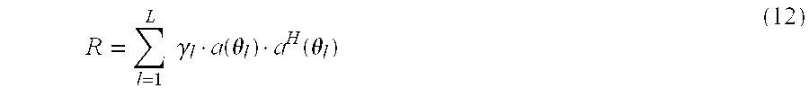
- The optimal transmission beamforming weight vectors are Eigenvectors corresponding to the two largest Eigenvalues of the downlink channel covariance matrix:
- R=E[h(t)·h H(t)] (11)
- where the expectation is conducted over all fading coefficients. Suppose the average power of each path is E|α l(t)|2=γl, the covariance matrix is given by:
- To achieve full diversity and maximized beamforming, this scheme requires only up to second order statistics of fading channel. Whereas the scheme involving the combining of the STTC technique with beamforming, beamforming weights are guaranteed to be optimal for Rayleigh/Rice fading channel only.
- The aforementioned schemes for systems employing either the STTC or STBC technique achieve diversity gain and optimal beamforming gain via combining the space-time coding techniques with the adaptive beamforming technique. The optimal beamforming weights may be obtained through either SVD or Eigen-decomposition. However, theoretical performance benefits achieved by the adaptive systems may be offset by the cost and complexities encountered in implementation. In wireless communications environments, received complex envelopes of signals vary rapidly due to fading. The adaptive beamformer must therefore “track” the change in the fading envelope so that beamforming weights always meet the optimality requirements. If the tracking performance using the adaptive algorithm is not sufficient, beamforming performances may degrade.
- For the beamforming technique, one simple alternative to the adaptive antenna system is the switched beam antenna system. The switched beam antenna system consists of multiple narrow beams, of which the beam considered best or has the strongest received power is used to serve a desired mobile terminal as it is moved through the coverage of a base station. The switched beam antenna system is more economical to implement, requiring only a static beamforming network, RF switch and control. Commercial deployments of switched beam antenna systems have demonstrated significant performance improvements over systems without multiple antennas. Nevertheless, the performance of the switched beam antenna system is considered by those skilled in the art to be inferior to that of the adaptive antenna system. Hence, because of the trade-off between implementation complexity and system performance, there is a technical prejudice that directly combining a switched beam antenna system with a space-time coding technique sacrifices system performance for the complexity of implementation.
- Therefore, there is a need for a system that provides the performance of an adaptive antenna system while possessing the implementation simplicity of a switched beam system for achieving diversity gain and beamforming gain simultaneously.
- In accordance with a first aspect of the invention, there is disclosed a method for selecting two beams in a switched beam antenna system for providing downlink communications in a downlink channel, the switched beam antenna system providing uplink reception and downlink transmission. The method comprises the steps of selecting a pair of beams based on the uplink reception of the switched beam antenna system, and determining from the pair of beams a corresponding pair of orthogonal beams. The method further comprises the step of providing the pair of orthogonal beams as a pair of transmit beams for the downlink transmission of the switched beam antenna system.
- In accordance with a second aspect of the invention, there is disclosed a switched beam antenna system for selecting two beams for providing downlink communications in a downlink channel, the switched beam antenna system further providing uplink reception and downlink transmission. The system comprises means for selecting a pair of beams based on the uplink reception of the switched beam antenna system, and means for determining from the pair of beams a corresponding pair of orthogonal beams. The system further comprises means for providing the pair of orthogonal beams as a pair of transmit beams for the downlink transmission of the switched beam antenna system.
- Embodiments of the invention are described hereinafter with reference to drawings, in which:
- FIG. 1 is a block diagram of a conventional downlink transmission system using the STBC technique;
- FIG. 2 is a block diagram of a conventional downlink transmission system combining an adaptive antenna system with the STBC technique;
- FIG. 3 illustrates a switched beam antenna system with twelve beams per sector;
- FIG. 4 illustrates the twelve beams shown in FIG. 3 being accentuated to show a twelve-beam pattern;
- FIG. 5 shows a beam pattern depicting measured powers of two pairs of beams corresponding to incoming paths of a system according to an embodiment of the invention combining the switched beam antenna system of FIG. 3 with the STBC technique;
- FIG. 6 is a flowchart of operations in a system according to an embodiment of the invention for selecting a pair of switched orthogonal beams using the switched beam antenna system of FIG. 3;
- FIGS. 7 a to 7 c are tabulated simulation results illustrating downlink BER performance vs. DOA for comparing the performance of the system of FIG. 5 with other systems;
- FIGS. 8 a to 8 c are tabulated simulation results illustrating downlink BER performance vs. transmit power (SNR) for comparing the performance of the system of FIG. 5 with other systems;
- FIG. 9 is a block diagram of a conventional multiple input-multiple output (MIMO) system; and
- FIG. 10 is a block diagram of another system according to an embodiment of the invention combining the switched beam antenna system of FIG. 3 with the MIMO technique.
- A system according to an embodiment of the invention is disclosed hereinafter to address the need for a system that provides the performance of an adaptive antenna system while possessing the implementation simplicity of a switched beam system for achieving diversity gain and beamforming gain simultaneously
- Such a system involves a practical, inexpensive, and robust downlink transmission scheme for achieving both diversity and beamforming gain based on some simple uplink measurements. In particular, the system approximates the maximum beamforming gain and achieves full diversity transmission as well by combining the STBC technique with a switched beam antenna system. The switched beam antenna system preferably has the same simple physical structure as that employed for uplink in a base station.
- The system involves a downlink diversity transmission scheme to combat fading effect for wireless communication systems where multiple antennas are employed in base stations while only a single antenna is employed in mobile terminals. A number of advantages are associated with such a system, which are described hereinafter.
- Firstly, the system includes a low cost switched beam system, and thus is simple to implement and cost effective. And in such a system, diversity transmission is fully obtained. At the same time, the beamforming gain is maximized to an approximating optimum value that is conventionally achieved by complex adaptive antenna systems. Furthermore, the scheme used in the system is applicable to frequency-selective fading channel when employed in CDMA and OFDM systems. The scheme is also applicable to either TDD systems or FDD systems. Additionally, the system by achieving combined beamforming and diversity transmission provides high spectrum efficiency, yet consumes less transmission power. Lastly, since a mobile terminal is usually limited by physical size and battery power, the system allows complicated processing to be performed at a base station, rather at the mobile terminal, thus reducing the mobile terminal complexity.
- The architecture of the system is similar to the conventional system shown in FIG. 2, with only one important distinction relating to two transmit
beamformers w 1 208 andw 2 210. In the system, the beamforming weights used in thebeamformers w 1 208 andw 2 210 are computed using processes, methods, and techniques described hereinafter. - FIG. 3 illustrates a switched
beam antenna system 300 which is used in the system, with twelvebeams 302 in each 120° sector, eachbeam 304 having a 10° width. Beamforming weights wi for an ith beam (i=1,2, . . . , 12) using a ULA antenna may be expressed as: - wi =[w i(1), w i(2),Λ, w i(M)]T (13)
- where w i(m)=exp[j·(m−1)·2π

- sin(φ i)] (m=1,2, . . . , M), φi is the main beam direction of the ith beam, d is the antenna element spacing usually set to 0.5λ, λ is the wavelength of the carrier, and M is the number of antenna elements. Other switched beam antenna systems with different antenna structure and/or beamforming weight generating methods may also be advantageously used.
- For conventional uplink or downlink switched beam systems, the objective is to select one best beam at a time for reception or transmission, respectively. A simple and efficient method to achieve this is to calculate the power level at the uplink receiver output in the system for each beam and select the beam with the highest output power for uplink reception or downlink transmission.
- When the conventional switched beam system is combined with the STBC technique for providing downlink transmission, two beams are needed, and correspondingly two sets of beamforming weights, at a time. As a direct extension from the single strongest beam technique, such a system has to select two strongest beams in terms of receiving power. However, this may cause performance degradation when compared with the adaptive beamforming system combined with STBC using beams determined by cost function from (8) to (10). The inferior performance of the “two strongest” beams technique is mainly due to the non-orthogonality, instead of lower accuracy relating to directivity to the desired mobile terminal, of the two strongest beams as opposed to adaptive beams. The first and second strongest beams are usually either adjacent, for example first and
second beams - To obtain full diversity gain, the system according to an embodiment of the invention therefore has to generate plenty of pairs of orthogonal beams for selection or switching. To approximate the maximum beamforming gain as well, the selected orthogonal beams should always direct to the signal path where most of the signal power lies. The Eigen-decomposition method is preferably applied in the system to produce orthogonal beams and corresponding beamforming weights, because the system not only produces orthogonal beams but also control the directivity of the beams produced. Based on the uplink measurement, two switched beams at directions of most signal power concentrated may be identified using processes, methods, and techniques described hereinafter. Based on the identified switched beams, Eigen-decomposition is applied to generate orthogonal beams while keeping the directivity of the conventional beams. The system generates each pair of orthogonal beams based on two or more switched beams.
- For two switched beams i and j (i≠j), the main beam directions are φ i and φj, respectively. With reference to equation (12), the covariance matrix of the corresponding downlink channels may be appropriately approximated by:
- {circumflex over (R)}=γ i ·a(φi)·a H(φi)+γj ·a(φj)·a H(φj)] (14)
- if multipath signals received at the mobile terminal are coming from the directions of beams i and j. The average powers γ i and γj may be measured at uplink, while for simplicity and minimum compromise in performance, may be set to γi=γj=0.5. A pair of orthogonal beams corresponding to switched beams i and j may be found as Eigenvectors of {circumflex over (R)} corresponding to two largest Eigenvalues. In this way, a mapping from any two switched beams i and j (i≠j) amongst all possible combination of two switched beams to the corresponding pair of orthogonal beams may be established.
- In the case where multipath signals are usually travel through N (N>2) switched beams, the mapping can be established similarly from all N switched beams to corresponding pairs of orthogonal beams. Since this mapping employs Eigen-decomposition is fixed once the communication system is established, the mapping procedure preferably using off-line processing, and therefore does not contribute to the complexity of the system. This is an advantage over adaptive antenna systems in which Eigen-decomposition is applied on-line.
- Thus if two conventional switched beams are selected, and the main beams of these two selected switched beams coincide with the directions of the multipath signals, the system uses the corresponding pair of orthogonal beams as transmit beams. Full diversity is then secured by the orthogonality of transmit beams. The maximum beamforming gain is approximated through off-line Eigen-decomposition of {circumflex over (R)} in (14), which is an appropriate estimate of R in (12).
- With reference to FIG. 4, in which the twelve beams shown in FIG. 3 is accentuated to show a twelve-
beam pattern 402, a preferred method by which the system captures the two switched beams that cover the directions of incoming multipath signals based on uplink measurements is described. In many scenarios, the selection of the two strongest switched beams works adequately and efficiently. However, the overall performance of the system may be degraded sharply when the directions of multipath signals are at the vicinity of the boundary between two adjacent beams. For example, using uplink measurements, the directions of twoincoming paths beam pattern 402. Usually, the two strongest beams for each incoming path are adjacent, and therefore in this case, either the pair comprising sixth 408 and seventh 410 beams or the pair comprising ninth 412 and tenth 414 beams provide the strongest beams. This leads to incorrect selection of switched beams that do not cover all the two incoming paths. To avoid such situations the method also includes an optimal switched beams selection technique described in greater detail hereinafter. - The method provides for the process of selecting the best two beams which ideally cover incoming paths with more power and less correlation with respect to each other. To this end, the method preferably uses a
power window threshold 504 of apower window 505 shown in FIG. 5, in which abeam pattern 502 depicts measured powers of the two pairs of beams corresponding to the incoming paths. Thepower window threshold 504 takes reference from the maximum power measured at the output of each of the beams, in this case thesixth beam 506. All the beams with output power within the employedpower window 505 are selected in this process, in this case the sixth 506, seventh 508, ninth 510, and tenth 512 beams. For each beam pair wi and wj formed from a combination of selecting two of the four beams in the selected beams pairs, a two-by-two matrix may be formed as:
- where W i,j=[wi wj] and R is the downlink channel covariance matrix which may be estimated from uplink measurements. For Time Division Duplex systems (TDD), R is the same as uplink channel covariance matrix and may be obtained using a simple averaging scheme:

- where u(n) denotes the uplink array signal sample at the n th instant of time and Nt is the total samples in the sampling time. For Frequency Division Duplex systems (FDD), the downlink channel covariance matrix may be obtained via frequency calibration processing to uplink channel covariance matrix Ru as described in Annex A.
- The diagonal elements in F i,j contribute to transmit power of two virtual paths while non-orthogonal elements contribute to the correlation between the two virtual paths. Taking into consideration the maximization of transmit power and minimization of cross correlation,
- Δ=det(F i,j) (17)
- may be used as a cost function to choose the beam pair having the maximum value of Δ among the selected beam pairs. Other cost functions may also be used for choosing the beam pair. And depending on the cost function used, the beam pair may be chosen based on maximum or minimum values of the cost function. For the case illustrated in FIG. 5, the system through the beam selection process selects one from the pair comprising the sixth 506 and seventh 508 beams and another from the pair comprising the ninth 510 and tenth 504 beams.
- The beam selection process does not substantially add to the computation load of the system because the power window threshold is preferably selected small enough that there are at most three or four beams selected from the beam pairs for scenarios similar to that illustrated in FIG. 5. In other scenarios, only two beams are typically selected. In the case of the twelve beams illustrated in FIG. 5, the default power window threshold is 3 dB from the upper extremity of the power window. For most of the time, the selection processing works the same as selecting the two strongest beams from the twelve beams. In the cases as illustrated in FIG. 5, four beams at most are selected and the cost function (17) is calculated six times, which is the number of the combination of selecting two from four beams. Also, it is noted that det(F i,j)=det(Fj,i).
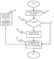
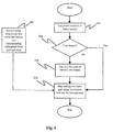
- The operation of the system for providing a practical and robust downlink transmission scheme achieving both diversity and beamforming gain through a switched orthogonal beam selection method is summarised using a flowchart shown in FIG. 6.
- In a
step 602 for setting up the antenna system, a set of mappings from any two switched beams to the corresponding orthogonal beam pair is prepared and stored in the system memory. The orthogonal beams are calculated as Eigenvectors corresponding to two largest Eigenvalues of matrix {circumflex over (R)} in (14). This step is performed off-line. - In a
step 604, all the beams with output power of uplink within power window threshold are selected. Then in afurther step 606, a check for the number of selected beams is performed. If the number of selected beams is two, anext step 608 is skipped and the system proceeds to astep 610. - In the
step 608, the cost function in (17) using (15) and (16) is calculated for all combinations of beam pairs among the selected beams. The two beams with a maximum value of the cost function are identified. - The orthogonal beam pair is then mapped from the two identified beams in the
step 610 as transmitting beams w1 and w2 using the mapping information stored in the system in thestep 602. - There is an alternative and equivalent method to select the two orthogonal switched beam pair when more than two beams are selected with output power within the employed
power window 505. Such a method requires the swapping ofstep 608 andstep 610. For each beam pair wi and wj formed from a combination of selecting two of the selected beams, the corresponding orthogonal beam pair is found first by the mapping operation. Then the cost function (17) is calculated for all orthogonal beam pairs. The orthogonal beam pair with the maximum value of Δ is selected as transmitting beams w1 and w2. - Although the switched orthogonal beam selection method in the system is derived herein in relation to frequency non-selective fading channels, it is also applicable to frequency selective channels where Code Division Multiplex Access (CDMA) systems or Orthogonal Frequency Division Multiplex (OFDM) systems are employed.
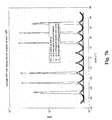
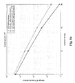
- The system performance in terms of bit error rate (BER) is evaluated through simulations described with reference to FIGS. 7 a to 7 c and 8 a to 8 c. It is generally assumed that a base station is equipped with 6-element and half-wavelength spaced ULA antenna while a mobile terminal has only single antenna. Twelve switched beams per sector are adopted for both uplink reception and downlink transmission. The communications channel is assumed Rayleigh fading with normalized Doppler shift 0.01 (maximum Doppler shift×sample time interval), and the channel is second order with angular spread set to 10°, 30°, and 60° representing small, moderate, and large angular spreads respectively. To verify performance vs. direction of arrival (DOA), it is generally assumed that the desired mobile terminal moves from one end of the sector to another to cover all the possible DOAs of the sector.
- The downlink BER performance vs. DOA and transmit power (SNR) is illustrated in FIGS. 7 a to 7 c and FIGS. 8a to 8 c, respectively. For comparison, performances of three alternative systems are also included. These include a system combining the STBC technique with adaptive beamforming scheme (system A), a system combining the STBC technique with a scheme using two strongest conventional switched beams (system B), and a system combining the STBC technique with a scheme using orthogonal beam pairs corresponding to the two strongest beams (system C). The system described hereinbefore is known as system D.
- For small angular spread case shown in FIGS. 7 a and 8 a, the system A is outperformed by all three other systems. The advantage in terms of power consumption for the same BER performance is about 1˜2.5 dB as shown in FIG. 8a. Because the angular spread is not wider than the width of the switched beams and the scenario shown in FIG. 5 does not occur, the system C works as well as the system D.
- For moderate and large angular spread wider than the width of switched beam, the performance of system C degrades severely especially when the worse scenarios happen as shown in FIGS. 7 b and 7 c. The performance difference between the systems B or C and the systems A or D may be as large as 5 dB as shown in FIGS. 8b and 8 c.
- It may therefore be concluded in the simulations that the performance of the system D, and therefore the system according to an embodiment of the invention, always approximates well to the conventional system A for all angular spreads.
- In the foregoing manner, a system is described which provides the performance of an adaptive antenna system while possessing the implementation simplicity of a switched beam system for achieving diversity gain and beamforming gain simultaneously.
- Although only a number of embodiments of the invention are disclosed, it will be apparent to one skilled in the art in view of this disclosure that numerous changes and/or modification can be made without departing from the scope and spirit of the invention.
- For example, the system may approximate the maximum beamforming gain and achieve diversity transmission as well by combining the STTC technique with a switched beam antenna system using the switched orthogonal beam selection method described hereinbefore.
- Alternatively, the system may use a Multiple Input Multiple Output (MIMO) wireless communication system in combination with a switched beam antenna system using the switched orthogonal beam selection method for achieving beamforming gain as well as diversity gain. For purposes of briefly describing a conventional MIMO system, a block diagram in FIG. 9 is referenced hereinafter which shows two transmitting
antennas 902 in abase station 904 and two receivingantennas 906 in amobile terminal 908. Such an MIMO system is known as a two input-two output MIMO system in which a serial sequence of original signals s(n), s(n+1) . . . 910 is de-multiplexed by ade-multiplexing module 912 into two parallel signal streams 914, which is then fed directly to the two transmittingantennas 902 for providing diversity transmission but without applying space-time coding as opposed to the other systems employing the STBC or STTC technique. The MIMO system is designed to achieve higher data throughput or transmission data rate and greater spectrum efficiency for wireless communication systems. From the architecture, it is clear that in the MIMO system, the transmission data rate is double compared to a system employing the STBC or STTC technique. At the receiver of themobile terminal 908, the two receivingantennas 906 providing diversity reception are employed to receive transmittedsignals 916 and the outputs of the receiver are passed into aMIMO detector 918, such as V-BLAST detector, to recover the original sequence of the original signals 910. In the case of flat fading channels, there are four channel coefficients in the MIMO system due to two receivingantennas 906 at the receiver of themobile terminal 908. - In the conventional MIMO system, the number of receiving antennas for providing diversity reception is required to be equal or more than the number of data streams or transmitting antennas for providing diversity transmission. Due to the size, cost, and complexity constraint, the number of receiving antennas in a mobile terminal is usually very small, which for example is two shown in FIG. 9. Therefore the number of transmitting antennas for providing diversity transmission in a base station using the conventional MIMO system is also limited.
- However, a switched beam antenna system having a transmitting antenna array with a larger number of transmitting antennas may be combined with the MIMO system to replace conventional transmitting antennas providing diversity transmission in the base station in order to obtain diversity gain as well as beamforming gain. This is akin to the replacement of transmitting antennas providing diversity transmission by a switched beam antenna system in the systems for combining with the STBC or STTC technique described hereinbefore.
- A block diagram of the alternative embodiment system combining the MIMO system (equivalent to two input-two output system) with the switched beam antenna system using a beamforming antenna array is shown in FIG. 10. A serial sequence of original signals s(n), s(n+1) . . . 1002 is first de-multiplexed by a
de-multiplexing module 1004 into two parallel data streams 1006. The twoparallel data streams 1006 are then passed into two transmit beamformers w1 and w2 1008 for beamforming processing, and passed on to asignal combiner 1012 which performs a simple summing function of the two beamforming processed inputs to produce a signal x(n) 1014 for transmission throughmultiple antennas 1016. - The physical channel is assumed to consist of L spatially separated
paths 1018 with directions of arrival (DOAs) θl and fading coefficients αl1(t) and αl2(t), l=1,Λ,L for receiving antennas 1 (1020A) and 2 (1020B) as shown in FIG. 10. The instantaneous channel response observed by the receiving antennas 1 (1020A) and 2 (1020B) are respectively:
- The signals coming from each path l=1,Λ,
L 1018 arriving at the two receivingantennas 1020A and 1020B experience different fading effects αl1(t) and αl2(t), which are assumed to be uncorrelated for receiving antennas providing diversity reception, although these have the same θl. Also, the covariance matrixes for the receiving antennas 1 (1020A) and 2 (1020B) are the same as long as the average power of eachpath 1018 is the same for the two receivingantennas 1020A and 1020B. The covariance matrixes for the receivingantennas 1020A and 1020B are very similar to the covariance matrix used in the system combining the STBC technique with the switched orthogonal beam selection method described hereinbefore. Therefore, in the system combining the switched beam antenna system and MIMO system, the using the switched orthogonal beam selection method is also applied for achieving fall diversity gain as well as approximated maximum beamforming gain. - For Frequency Division Duplex systems (FDD), the downlink channel covariance matrix (DCCM) R d may be obtained via frequency calibration processing to uplink channel covariance matrix (UCCM) Ru as disclosed in Y-C. Liang and F. Chin, “Downlink beamforming methods for capacity enhancement in wireless communication systems”, Singapore Patent Application No. 9904733.4. It is shown that there is deterministic relationship between Ru and Rd based on the fact that the Direction of Arrivals (DOAs) of signals remain unchanged for uplink and downlink transmissions. That is:
- r d =C·r u (A.1)
- where
- r u=vec(R u) (A.2)
- r d=vec(R d) (A.3)
- vec( ) is a column-vectorization operator which forms a column vector by aligning columns of the matrix one by one, i.e. for any M-by-N matrix X={x ij}(i=1 . . . M, j=1 . . . N), the ((m−1)*M+n)th element of the MN-by-1 vector vec(X) is xmn, and C is the so called Frequency Calibration (FC) matrix, a function of uplink and downlink carrier frequency, geometry of the antenna array, and cell sectorization. That is to say, given uplink and downlink carrier frequency, geometry of the antenna array, and cell sectorization after setup of the communication system, C is a fixed matrix. It can be calculated off-line as:

- where
- Q u=[vec(Q u (−M+1)),vec(Q u (−M+2)),Λvec(Q u (M−1))]
- Q d=[vec(Q d (−M+1)),vec(Q d (−M+2)),Λvec(Q d (M−1))]
-

- a u(θ) and ad(θ) are the uplink and downlink M-by-1 steering vector at DOA θ respectively, S is the number of sector, and M is the number of antenna elements. Therefore, with FC matrix C in hand, rd may be estimated from Ru using formula (A.1) and (A.2) and reconstruct Rd from rd by inverse procedure of vectorization operation (A.3).
Claims (20)
Priority Applications (3)
| Application Number | Priority Date | Filing Date | Title |
|---|---|---|---|
| US10/116,240 US6850741B2 (en) | 2002-04-04 | 2002-04-04 | Method for selecting switched orthogonal beams for downlink diversity transmission |
| AU2003217155A AU2003217155A1 (en) | 2002-04-04 | 2003-04-04 | Method for selecting switched orthogonal beams for downlink diversity transmission |
| PCT/SG2003/000073 WO2003085857A1 (en) | 2002-04-04 | 2003-04-04 | Method for selecting switched orthogonal beams for downlink diversity transmission |
Applications Claiming Priority (1)
| Application Number | Priority Date | Filing Date | Title |
|---|---|---|---|
| US10/116,240 US6850741B2 (en) | 2002-04-04 | 2002-04-04 | Method for selecting switched orthogonal beams for downlink diversity transmission |
Publications (2)
| Publication Number | Publication Date |
|---|---|
| US20030190897A1 true US20030190897A1 (en) | 2003-10-09 |
| US6850741B2 US6850741B2 (en) | 2005-02-01 |
Family
ID=28673926
Family Applications (1)
| Application Number | Title | Priority Date | Filing Date |
|---|---|---|---|
| US10/116,240 Expired - Lifetime US6850741B2 (en) | 2002-04-04 | 2002-04-04 | Method for selecting switched orthogonal beams for downlink diversity transmission |
Country Status (3)
| Country | Link |
|---|---|
| US (1) | US6850741B2 (en) |
| AU (1) | AU2003217155A1 (en) |
| WO (1) | WO2003085857A1 (en) |
Cited By (89)
| Publication number | Priority date | Publication date | Assignee | Title |
|---|---|---|---|---|
| US20030235255A1 (en) * | 2002-06-24 | 2003-12-25 | Ketchum John W. | Signal processing with channel eigenmode decomposition and channel inversion for MIMO systems |
| US20040095907A1 (en) * | 2000-06-13 | 2004-05-20 | Agee Brian G. | Method and apparatus for optimization of wireless multipoint electromagnetic communication networks |
| WO2004095851A3 (en) * | 2003-04-23 | 2005-02-24 | Flarion Technologies Inc | Methods and apparatus of enhancing performance in wireless communication systems |
| US20050096090A1 (en) * | 2003-10-30 | 2005-05-05 | Shirish Nagaraj | Method and apparatus for providing user specific downlink beamforming in a fixed beam network |
| US20050101353A1 (en) * | 2003-09-25 | 2005-05-12 | Interdigital Technology Corporation | Method and system for enhancing reception of wireless communication signals |
| US20050136963A1 (en) * | 2003-12-18 | 2005-06-23 | Motorola, Inc. | Method and apparatus for optimal multiple beam transmit weightings for beam to beam handoff in a switched beam system |
| US20060104382A1 (en) * | 2004-10-27 | 2006-05-18 | Samsung Electronics Co., Ltd. | Method and apparatus for transmitting/receiving signals in multiple input multiple output wireless communication system employing beam forming scheme |
| US20060120477A1 (en) * | 2004-12-07 | 2006-06-08 | Adaptix, Inc. | Cooperative MIMO in multicell wireless networks |
| US7103325B1 (en) * | 2002-04-05 | 2006-09-05 | Nortel Networks Limited | Adaptive modulation and coding |
| US20060276227A1 (en) * | 2005-06-02 | 2006-12-07 | Qualcomm Incorporated | Multi-antenna station with distributed antennas |
| US20070019583A1 (en) * | 2003-04-23 | 2007-01-25 | Rajiv Laroia | In-band rate indicator methods and apparatus |
| US20070049347A1 (en) * | 2005-08-29 | 2007-03-01 | Navini Networks, Inc. | Method and system for partitioning an antenna array and applying multiple-input-multiple-output and beamforming mechanisms |
| US7194237B2 (en) * | 2002-07-30 | 2007-03-20 | Ipr Licensing Inc. | System and method for multiple-input multiple-output (MIMO) radio communication |
| US20070064641A1 (en) * | 2004-04-23 | 2007-03-22 | Rajiv Laroia | Methods and apparatus of enhancing performance in wireless communication systems |
| US20080039146A1 (en) * | 2006-08-10 | 2008-02-14 | Navini Networks, Inc. | Method and system for improving robustness of interference nulling for antenna arrays |
| US20080102881A1 (en) * | 2006-10-25 | 2008-05-01 | Samsung Electronics Co., Ltd. | Method and apparatus for adaptively allocating transmission power for beam-forming combined with OSTBCs in a distributed wireless communication system |
| US20080102764A1 (en) * | 2006-10-30 | 2008-05-01 | Thornton Steven D | Methods and systems for signal selection |
| US20080117961A1 (en) * | 2006-11-22 | 2008-05-22 | Samsung Electronics Co.; Ltd | Method and apparatus of adaptively allocating transmission power for beamforming combined with orthogonal space-time block codes based on symbol error rate in distributed wireless communication system |
| US20080267306A1 (en) * | 2007-04-27 | 2008-10-30 | Texas Instruments Incorporated | Systems and Methods for Low-Complexity Maximum-Likelihood MIMO Detection |
| US20080310541A1 (en) * | 2007-06-18 | 2008-12-18 | Joonsuk Kim | Method and system for sfbc/stbc in a diversity transmission system using alamouti codes |
| US20090129454A1 (en) * | 2005-05-12 | 2009-05-21 | Qualcomm Incorporated | Rate selection with margin sharing |
| US20090137237A1 (en) * | 2005-09-26 | 2009-05-28 | Sharp Kabushiki Kaisha | Wireless communication system, base station device, mobile station device, and macrodiversity selection method |
| US20090160622A1 (en) * | 2007-12-20 | 2009-06-25 | Frederic Bauchot | Dividing tagged items into subsets |
| US20090323643A1 (en) * | 2008-06-27 | 2009-12-31 | Sang-Woon Jeon | Method for cooperative multi-antenna communication |
| US20100119001A1 (en) * | 2002-10-25 | 2010-05-13 | Qualcomm Incorporated | Mimo system with multiple spatial multiplexing modes |
| US20100246703A1 (en) * | 2009-03-31 | 2010-09-30 | Orlik Philip V | Unified STTC Encoder for WAVE Transceivers |
| US20100311469A1 (en) * | 2003-02-05 | 2010-12-09 | Nortel Networks Limited | Downlink and uplink array and beamforming arrangement for wireless communication networks |
| US20100326888A1 (en) * | 2009-06-25 | 2010-12-30 | China Petroleum & Chemical Corporation | Catalytic cracking catalyst having a higher selectivity, processing method and use thereof |
| US8045512B2 (en) | 2005-10-27 | 2011-10-25 | Qualcomm Incorporated | Scalable frequency band operation in wireless communication systems |
| US8073072B2 (en) | 2003-11-04 | 2011-12-06 | Qualcomm Atheros, Inc. | Multiple-input multiple-output system and method |
| US20110299441A1 (en) * | 2010-06-07 | 2011-12-08 | Entropic Communications, Inc. | Method and Apparatus for Real Time Multiplexing with Transmitter and Antenna Array Elements |
| US8098569B2 (en) | 2000-09-13 | 2012-01-17 | Qualcomm Incorporated | Signaling method in an OFDM multiple access system |
| US20120076031A1 (en) * | 2002-05-13 | 2012-03-29 | Interdigital Technology Corporation | Resource allocation to users in slotted code division multiple access systems using beams |
| EP2457286A1 (en) * | 2009-07-20 | 2012-05-30 | Telcordia Technologies, Inc. | System and method for improving mimo performance of vehicular based wireless communications |
| US8228809B1 (en) | 2007-12-21 | 2012-07-24 | Adaptix, Inc. | Intelligent mode switching in communication networks |
| US8345639B2 (en) | 2010-06-14 | 2013-01-01 | Raytheon Company | Broad propagation pattern antenna |
| US8396153B1 (en) | 2004-12-07 | 2013-03-12 | Adaptix, Inc. | Cooperative MIMO in multicell wireless networks |
| US8446892B2 (en) | 2005-03-16 | 2013-05-21 | Qualcomm Incorporated | Channel structures for a quasi-orthogonal multiple-access communication system |
| US8462859B2 (en) | 2005-06-01 | 2013-06-11 | Qualcomm Incorporated | Sphere decoding apparatus |
| US8477684B2 (en) | 2005-10-27 | 2013-07-02 | Qualcomm Incorporated | Acknowledgement of control messages in a wireless communication system |
| US8565194B2 (en) | 2005-10-27 | 2013-10-22 | Qualcomm Incorporated | Puncturing signaling channel for a wireless communication system |
| US8582509B2 (en) | 2005-10-27 | 2013-11-12 | Qualcomm Incorporated | Scalable frequency band operation in wireless communication systems |
| US8582548B2 (en) | 2005-11-18 | 2013-11-12 | Qualcomm Incorporated | Frequency division multiple access schemes for wireless communication |
| US8599945B2 (en) | 2005-06-16 | 2013-12-03 | Qualcomm Incorporated | Robust rank prediction for a MIMO system |
| US8611284B2 (en) | 2005-05-31 | 2013-12-17 | Qualcomm Incorporated | Use of supplemental assignments to decrement resources |
| US8644292B2 (en) | 2005-08-24 | 2014-02-04 | Qualcomm Incorporated | Varied transmission time intervals for wireless communication system |
| US20140079097A1 (en) * | 2011-11-04 | 2014-03-20 | Alcatel-Lucent Usa Inc. | Method and apparatus to generate virtual sector wide static beams using phase shift transmit diversity |
| US8693405B2 (en) | 2005-10-27 | 2014-04-08 | Qualcomm Incorporated | SDMA resource management |
| US8711763B2 (en) | 2002-10-25 | 2014-04-29 | Qualcomm Incorporated | Random access for wireless multiple-access communication systems |
| US8750151B2 (en) | 2002-10-25 | 2014-06-10 | Qualcomm Incorporated | Channel calibration for a time division duplexed communication system |
| US8831607B2 (en) | 2006-01-05 | 2014-09-09 | Qualcomm Incorporated | Reverse link other sector communication |
| US8867461B2 (en) | 2008-08-11 | 2014-10-21 | Lg Electronics Inc. | Method of transmitting or receiving uplink signals and equipment therefor |
| US8873365B2 (en) | 2002-10-25 | 2014-10-28 | Qualcomm Incorporated | Transmit diversity processing for a multi-antenna communication system |
| US8879511B2 (en) | 2005-10-27 | 2014-11-04 | Qualcomm Incorporated | Assignment acknowledgement for a wireless communication system |
| US8885628B2 (en) | 2005-08-08 | 2014-11-11 | Qualcomm Incorporated | Code division multiplexing in a single-carrier frequency division multiple access system |
| US8913529B2 (en) | 2002-10-25 | 2014-12-16 | Qualcomm Incorporated | MIMO WLAN system |
| US8917654B2 (en) | 2005-04-19 | 2014-12-23 | Qualcomm Incorporated | Frequency hopping design for single carrier FDMA systems |
| US20150139347A1 (en) * | 2013-11-21 | 2015-05-21 | The Hong Kong University Of Science And Technology | Weighted sum data rate maximization using linear transceivers in a full-duplex multi-user mimo system |
| US9088384B2 (en) | 2005-10-27 | 2015-07-21 | Qualcomm Incorporated | Pilot symbol transmission in wireless communication systems |
| US9130810B2 (en) | 2000-09-13 | 2015-09-08 | Qualcomm Incorporated | OFDM communications methods and apparatus |
| US9137822B2 (en) | 2004-07-21 | 2015-09-15 | Qualcomm Incorporated | Efficient signaling over access channel |
| US9136974B2 (en) | 2005-08-30 | 2015-09-15 | Qualcomm Incorporated | Precoding and SDMA support |
| US9144060B2 (en) | 2005-10-27 | 2015-09-22 | Qualcomm Incorporated | Resource allocation for shared signaling channels |
| US9143305B2 (en) | 2005-03-17 | 2015-09-22 | Qualcomm Incorporated | Pilot signal transmission for an orthogonal frequency division wireless communication system |
| US9148256B2 (en) | 2004-07-21 | 2015-09-29 | Qualcomm Incorporated | Performance based rank prediction for MIMO design |
| US9154274B2 (en) | 2002-10-25 | 2015-10-06 | Qualcomm Incorporated | OFDM communication system with multiple OFDM symbol sizes |
| US9154211B2 (en) | 2005-03-11 | 2015-10-06 | Qualcomm Incorporated | Systems and methods for beamforming feedback in multi antenna communication systems |
| US9172453B2 (en) | 2005-10-27 | 2015-10-27 | Qualcomm Incorporated | Method and apparatus for pre-coding frequency division duplexing system |
| US9179319B2 (en) | 2005-06-16 | 2015-11-03 | Qualcomm Incorporated | Adaptive sectorization in cellular systems |
| US9184870B2 (en) | 2005-04-01 | 2015-11-10 | Qualcomm Incorporated | Systems and methods for control channel signaling |
| US9209956B2 (en) | 2005-08-22 | 2015-12-08 | Qualcomm Incorporated | Segment sensitive scheduling |
| US9210651B2 (en) | 2005-10-27 | 2015-12-08 | Qualcomm Incorporated | Method and apparatus for bootstraping information in a communication system |
| US9225488B2 (en) | 2005-10-27 | 2015-12-29 | Qualcomm Incorporated | Shared signaling channel |
| US9225416B2 (en) | 2005-10-27 | 2015-12-29 | Qualcomm Incorporated | Varied signaling channels for a reverse link in a wireless communication system |
| US9246560B2 (en) | 2005-03-10 | 2016-01-26 | Qualcomm Incorporated | Systems and methods for beamforming and rate control in a multi-input multi-output communication systems |
| US9307544B2 (en) | 2005-04-19 | 2016-04-05 | Qualcomm Incorporated | Channel quality reporting for adaptive sectorization |
| US9312935B2 (en) | 2002-10-25 | 2016-04-12 | Qualcomm Incorporated | Pilots for MIMO communication systems |
| US9444532B1 (en) * | 2015-02-23 | 2016-09-13 | Wisconsin Alumni Research Foundation | Wideband transceiver for antenna array |
| US9461859B2 (en) | 2005-03-17 | 2016-10-04 | Qualcomm Incorporated | Pilot signal transmission for an orthogonal frequency division wireless communication system |
| US9473269B2 (en) | 2003-12-01 | 2016-10-18 | Qualcomm Incorporated | Method and apparatus for providing an efficient control channel structure in a wireless communication system |
| US9520972B2 (en) | 2005-03-17 | 2016-12-13 | Qualcomm Incorporated | Pilot signal transmission for an orthogonal frequency division wireless communication system |
| WO2017054713A1 (en) * | 2015-09-28 | 2017-04-06 | Huawei Technologies Co., Ltd. | System and method for large scale multiple input multiple output communications |
| US9660776B2 (en) | 2005-08-22 | 2017-05-23 | Qualcomm Incorporated | Method and apparatus for providing antenna diversity in a wireless communication system |
| EP3197067A4 (en) * | 2014-07-31 | 2017-07-26 | Huawei Technologies Co. Ltd. | Data transmission method and apparatus |
| US10205491B2 (en) | 2015-09-28 | 2019-02-12 | Futurewei Technologies, Inc. | System and method for large scale multiple input multiple output communications |
| US10735080B2 (en) | 2016-08-10 | 2020-08-04 | Huawei Technologies Co., Ltd. | Transmission scheme indication method, and data transmission method, apparatus, and system |
| US10917161B2 (en) * | 2017-03-17 | 2021-02-09 | Sony Corporation | Electronic device and method for wireless communication |
| US20220225186A1 (en) * | 2021-01-08 | 2022-07-14 | Qualcomm Incorporated | Measurement of number of spatial-domain streams available for multiplexing |
| EP4038759A4 (en) * | 2019-09-30 | 2023-05-17 | Telefonaktiebolaget LM Ericsson (publ) | Method and network device for beam vector selection |
Families Citing this family (35)
| Publication number | Priority date | Publication date | Assignee | Title |
|---|---|---|---|---|
| US7952511B1 (en) | 1999-04-07 | 2011-05-31 | Geer James L | Method and apparatus for the detection of objects using electromagnetic wave attenuation patterns |
| KR100795824B1 (en) * | 2001-12-08 | 2008-01-17 | 주식회사 세스텍 | Signal Processing Method and Apparatus for Antenna Array System Providing a Diversity Gain |
| US20040004951A1 (en) * | 2002-07-05 | 2004-01-08 | Interdigital Technology Corporation | Method for performing wireless switching |
| WO2004042983A2 (en) * | 2002-11-04 | 2004-05-21 | Vivato, Inc. | Forced beam switching in wireless communication systems having smart antennas |
| AU2003285138A1 (en) | 2002-11-04 | 2004-06-07 | Vivato Inc | Directed wireless communication |
| US7505788B1 (en) * | 2002-12-09 | 2009-03-17 | Marvell International, Ltd. | Spatial multiplexing with antenna and constellation selection for correlated MIMO fading channels |
| JP4514463B2 (en) * | 2003-02-12 | 2010-07-28 | パナソニック株式会社 | Transmitting apparatus and wireless communication method |
| US7302238B2 (en) * | 2003-04-25 | 2007-11-27 | Samsung Electronics Co., Ltd. | Transmit diversity system, method and computer program product |
| US7310537B2 (en) * | 2003-04-25 | 2007-12-18 | Nokia Corporation | Communication on multiple beams between stations |
| JP3799030B2 (en) * | 2003-05-09 | 2006-07-19 | 松下電器産業株式会社 | CDMA transmitter and CDMA transmission method |
| US7263335B2 (en) * | 2004-07-19 | 2007-08-28 | Purewave Networks, Inc. | Multi-connection, non-simultaneous frequency diversity in radio communication systems |
| WO2006017850A2 (en) * | 2004-08-12 | 2006-02-16 | Interdigital Technology Corporation | Method and apparatus for reducing antenna correlation |
| US7551902B2 (en) * | 2004-12-28 | 2009-06-23 | Nokia Corporation | Method and apparatus to increase the diversity order for a multi-carrier FDM system |
| US7565113B2 (en) * | 2005-03-29 | 2009-07-21 | Sony Corporation | Method and apparatus to resist fading in mimo and simo wireless systems |
| WO2007043459A1 (en) * | 2005-10-07 | 2007-04-19 | Nec Corporation | Mimo radio communication system and method using a plurality of base stations and mobile stations |
| US7546103B1 (en) | 2005-10-07 | 2009-06-09 | Marvell International Ltd. | Antenna diversity system and method |
| US8340071B2 (en) * | 2005-10-26 | 2012-12-25 | Intel Corporation | Systems for communicating using multiple frequency bands in a wireless network |
| US20070099669A1 (en) * | 2005-10-26 | 2007-05-03 | Sadri Ali S | Communication signaling using multiple frequency bands in a wireless network |
| US7720036B2 (en) * | 2005-10-26 | 2010-05-18 | Intel Corporation | Communication within a wireless network using multiple frequency bands |
| US9084260B2 (en) | 2005-10-26 | 2015-07-14 | Intel Corporation | Systems for communicating using multiple frequency bands in a wireless network |
| US7653163B2 (en) * | 2005-10-26 | 2010-01-26 | Intel Corporation | Systems for communicating using multiple frequency bands in a wireless network |
| US7657244B2 (en) * | 2005-10-27 | 2010-02-02 | Samsung Electronics Co., Ltd. | Methods of antenna selection for downlink MIMO-OFDM transmission over spatial correlated channels |
| US20070126585A1 (en) * | 2005-12-06 | 2007-06-07 | Symbol Technologies, Inc. | System integration of RFID and MIMO technologies |
| US7940640B2 (en) | 2006-01-20 | 2011-05-10 | Nortel Networks Limited | Adaptive orthogonal scheduling for virtual MIMO system |
| US7697959B2 (en) * | 2006-10-10 | 2010-04-13 | Intel Corporation | Adaptive multiple-antenna systems with omni-directional and sector-directional antenna modes |
| US9622216B2 (en) * | 2006-10-20 | 2017-04-11 | Avago Technologies General Ip (Singapore) Ptd. Ltd | Method and system for low rate MAC/PHY for 60 GHz transmission |
| US7551682B2 (en) * | 2006-10-25 | 2009-06-23 | Cisco Technology, Inc. | Method for improving the performance of a wireless network utilizing beamforming weighting vectors |
| US20080117865A1 (en) * | 2006-11-17 | 2008-05-22 | Li Guoqing C | Communication in a wireless network using multiple antennae |
| US7689171B2 (en) * | 2006-11-27 | 2010-03-30 | Intel Corporation | Reducing interference in a wireless network via antenna selection |
| US7983366B2 (en) | 2006-12-05 | 2011-07-19 | Intel Corporation | Transmission signaling techniques to enhance receiver interference mitigation performance |
| WO2009037580A2 (en) * | 2007-07-16 | 2009-03-26 | Nortel Networks Limited | Providing space division multiple access in a wireless network |
| US8494466B2 (en) * | 2008-03-26 | 2013-07-23 | Broadcom Corporation | Selecting receiver chains of a mobile unit for receiving wireless signals |
| JP4539891B2 (en) * | 2008-08-11 | 2010-09-08 | 岩崎通信機株式会社 | Wireless communication method, wireless communication system, and wireless communication apparatus using multi-antenna |
| WO2010018927A2 (en) * | 2008-08-11 | 2010-02-18 | Lg Electronics Inc. | Method of transmitting or receiving uplink signals and equipment therefor |
| KR101881847B1 (en) * | 2012-02-21 | 2018-08-24 | 삼성전자주식회사 | Method and apparatus for transmitting and receiving signal in a communication system |
Citations (5)
| Publication number | Priority date | Publication date | Assignee | Title |
|---|---|---|---|---|
| US6104935A (en) * | 1997-05-05 | 2000-08-15 | Nortel Networks Corporation | Down link beam forming architecture for heavily overlapped beam configuration |
| US20030032453A1 (en) * | 2000-01-28 | 2003-02-13 | Marcos Katz | Diversity transmission |
| US6580701B1 (en) * | 1997-07-04 | 2003-06-17 | Nokia Corporation | Interpretation of a received signal |
| US20030151553A1 (en) * | 2000-12-23 | 2003-08-14 | Juha Ylitalo | Base station, base station module and method for direction of arrival estimation |
| US20040014432A1 (en) * | 2000-03-23 | 2004-01-22 | U.S. Philips Corporation | Antenna diversity arrangement |
Family Cites Families (4)
| Publication number | Priority date | Publication date | Assignee | Title |
|---|---|---|---|---|
| US5995497A (en) * | 1996-04-23 | 1999-11-30 | At&T Corp. | Method and apparatus for switching code division multiple access modulated beams in a satellite |
| US6167286A (en) * | 1997-06-05 | 2000-12-26 | Nortel Networks Corporation | Multi-beam antenna system for cellular radio base stations |
| US6470192B1 (en) * | 1999-08-16 | 2002-10-22 | Telefonaktiebolaget Lm Ericcson (Publ) | Method of an apparatus for beam reduction and combining in a radio communications system |
| DE10051133A1 (en) * | 2000-10-16 | 2002-05-02 | Siemens Ag | Beamforming method |
-
2002
- 2002-04-04 US US10/116,240 patent/US6850741B2/en not_active Expired - Lifetime
-
2003
- 2003-04-04 WO PCT/SG2003/000073 patent/WO2003085857A1/en not_active Application Discontinuation
- 2003-04-04 AU AU2003217155A patent/AU2003217155A1/en not_active Abandoned
Patent Citations (5)
| Publication number | Priority date | Publication date | Assignee | Title |
|---|---|---|---|---|
| US6104935A (en) * | 1997-05-05 | 2000-08-15 | Nortel Networks Corporation | Down link beam forming architecture for heavily overlapped beam configuration |
| US6580701B1 (en) * | 1997-07-04 | 2003-06-17 | Nokia Corporation | Interpretation of a received signal |
| US20030032453A1 (en) * | 2000-01-28 | 2003-02-13 | Marcos Katz | Diversity transmission |
| US20040014432A1 (en) * | 2000-03-23 | 2004-01-22 | U.S. Philips Corporation | Antenna diversity arrangement |
| US20030151553A1 (en) * | 2000-12-23 | 2003-08-14 | Juha Ylitalo | Base station, base station module and method for direction of arrival estimation |
Cited By (166)
| Publication number | Priority date | Publication date | Assignee | Title |
|---|---|---|---|---|
| US20040095907A1 (en) * | 2000-06-13 | 2004-05-20 | Agee Brian G. | Method and apparatus for optimization of wireless multipoint electromagnetic communication networks |
| US8098569B2 (en) | 2000-09-13 | 2012-01-17 | Qualcomm Incorporated | Signaling method in an OFDM multiple access system |
| US8098568B2 (en) | 2000-09-13 | 2012-01-17 | Qualcomm Incorporated | Signaling method in an OFDM multiple access system |
| US11032035B2 (en) | 2000-09-13 | 2021-06-08 | Qualcomm Incorporated | Signaling method in an OFDM multiple access system |
| US10313069B2 (en) | 2000-09-13 | 2019-06-04 | Qualcomm Incorporated | Signaling method in an OFDM multiple access system |
| US9426012B2 (en) | 2000-09-13 | 2016-08-23 | Qualcomm Incorporated | Signaling method in an OFDM multiple access system |
| US9130810B2 (en) | 2000-09-13 | 2015-09-08 | Qualcomm Incorporated | OFDM communications methods and apparatus |
| US7103325B1 (en) * | 2002-04-05 | 2006-09-05 | Nortel Networks Limited | Adaptive modulation and coding |
| US20120076031A1 (en) * | 2002-05-13 | 2012-03-29 | Interdigital Technology Corporation | Resource allocation to users in slotted code division multiple access systems using beams |
| US9380588B2 (en) * | 2002-05-13 | 2016-06-28 | Interdigital Technology Corporation | Resource allocation to users in slotted code division multiple access system using beams |
| US7613248B2 (en) * | 2002-06-24 | 2009-11-03 | Qualcomm Incorporated | Signal processing with channel eigenmode decomposition and channel inversion for MIMO systems |
| US20030235255A1 (en) * | 2002-06-24 | 2003-12-25 | Ketchum John W. | Signal processing with channel eigenmode decomposition and channel inversion for MIMO systems |
| US7194237B2 (en) * | 2002-07-30 | 2007-03-20 | Ipr Licensing Inc. | System and method for multiple-input multiple-output (MIMO) radio communication |
| US9031097B2 (en) * | 2002-10-25 | 2015-05-12 | Qualcomm Incorporated | MIMO system with multiple spatial multiplexing modes |
| US8913529B2 (en) | 2002-10-25 | 2014-12-16 | Qualcomm Incorporated | MIMO WLAN system |
| US20100119001A1 (en) * | 2002-10-25 | 2010-05-13 | Qualcomm Incorporated | Mimo system with multiple spatial multiplexing modes |
| US9013974B2 (en) | 2002-10-25 | 2015-04-21 | Qualcomm Incorporated | MIMO WLAN system |
| US8873365B2 (en) | 2002-10-25 | 2014-10-28 | Qualcomm Incorporated | Transmit diversity processing for a multi-antenna communication system |
| US9312935B2 (en) | 2002-10-25 | 2016-04-12 | Qualcomm Incorporated | Pilots for MIMO communication systems |
| US9154274B2 (en) | 2002-10-25 | 2015-10-06 | Qualcomm Incorporated | OFDM communication system with multiple OFDM symbol sizes |
| US8934329B2 (en) | 2002-10-25 | 2015-01-13 | Qualcomm Incorporated | Transmit diversity processing for a multi-antenna communication system |
| US9240871B2 (en) | 2002-10-25 | 2016-01-19 | Qualcomm Incorporated | MIMO WLAN system |
| US8750151B2 (en) | 2002-10-25 | 2014-06-10 | Qualcomm Incorporated | Channel calibration for a time division duplexed communication system |
| US9048892B2 (en) | 2002-10-25 | 2015-06-02 | Qualcomm Incorporated | MIMO system with multiple spatial multiplexing modes |
| US10382106B2 (en) | 2002-10-25 | 2019-08-13 | Qualcomm Incorporated | Pilots for MIMO communication systems |
| US9967005B2 (en) | 2002-10-25 | 2018-05-08 | Qualcomm Incorporated | Pilots for MIMO communication systems |
| US8711763B2 (en) | 2002-10-25 | 2014-04-29 | Qualcomm Incorporated | Random access for wireless multiple-access communication systems |
| US8868095B2 (en) | 2003-02-05 | 2014-10-21 | Apple Inc. | Downlink and uplink array and beamforming arrangement for wireless communication networks |
| US20100311469A1 (en) * | 2003-02-05 | 2010-12-09 | Nortel Networks Limited | Downlink and uplink array and beamforming arrangement for wireless communication networks |
| US8406812B2 (en) * | 2003-02-05 | 2013-03-26 | Apple, Inc. | Downlink and uplink array and beamforming arrangement for wireless communication networks |
| US20070019583A1 (en) * | 2003-04-23 | 2007-01-25 | Rajiv Laroia | In-band rate indicator methods and apparatus |
| US7142864B2 (en) * | 2003-04-23 | 2006-11-28 | Qualcomm, Incorporated | Methods and apparatus of enhancing performance in wireless communication systems |
| US8892110B2 (en) | 2003-04-23 | 2014-11-18 | Qualcomm Incorporated | Methods and apparatus of enhancing performance in wireless communication systems |
| US20050181799A1 (en) * | 2003-04-23 | 2005-08-18 | Rajiv Laroia | Methods and apparatus of enhancing performance in wireless communication systems |
| US8452294B2 (en) | 2003-04-23 | 2013-05-28 | Qualcomm Incorporated | In-band ate indicator methods and apparatus |
| WO2004095851A3 (en) * | 2003-04-23 | 2005-02-24 | Flarion Technologies Inc | Methods and apparatus of enhancing performance in wireless communication systems |
| US7340281B2 (en) * | 2003-09-25 | 2008-03-04 | Interdigital Technology Corporation | Method and system for enhancing reception of wireless communication signals |
| US20050101353A1 (en) * | 2003-09-25 | 2005-05-12 | Interdigital Technology Corporation | Method and system for enhancing reception of wireless communication signals |
| US7333835B2 (en) | 2003-10-30 | 2008-02-19 | Lucent Technologies Inc. | Method and apparatus for providing user specific downlink beamforming in a fixed beam network |
| US7054664B2 (en) * | 2003-10-30 | 2006-05-30 | Lucent Technologies Inc. | Method and apparatus for providing user specific downlink beamforming in a fixed beam network |
| US20060194548A1 (en) * | 2003-10-30 | 2006-08-31 | Shirish Nagaraj | Method and apparatus for providing user specific downlink beamforming in a fixed beam network |
| US20050096090A1 (en) * | 2003-10-30 | 2005-05-05 | Shirish Nagaraj | Method and apparatus for providing user specific downlink beamforming in a fixed beam network |
| US8989294B2 (en) | 2003-11-04 | 2015-03-24 | Qualcomm Incorporated | Multiple-input multiple-output system and method |
| US8073072B2 (en) | 2003-11-04 | 2011-12-06 | Qualcomm Atheros, Inc. | Multiple-input multiple-output system and method |
| US8599953B2 (en) | 2003-11-04 | 2013-12-03 | Qualcomm Incorporated | Multiple-input multiple-output system and method |
| US9876609B2 (en) | 2003-12-01 | 2018-01-23 | Qualcomm Incorporated | Method and apparatus for providing an efficient control channel structure in a wireless communication system |
| US10742358B2 (en) | 2003-12-01 | 2020-08-11 | Qualcomm Incorporated | Method and apparatus for providing an efficient control channel structure in a wireless communication system |
| US9473269B2 (en) | 2003-12-01 | 2016-10-18 | Qualcomm Incorporated | Method and apparatus for providing an efficient control channel structure in a wireless communication system |
| US20050136963A1 (en) * | 2003-12-18 | 2005-06-23 | Motorola, Inc. | Method and apparatus for optimal multiple beam transmit weightings for beam to beam handoff in a switched beam system |
| US7242955B2 (en) * | 2003-12-18 | 2007-07-10 | Motorola, Inc. | Method and apparatus for optimal multiple beam transmit weightings for beam to beam handoff in a switched beam system |
| US9049722B2 (en) * | 2004-04-23 | 2015-06-02 | Qualcomm Incorporated | Methods and apparatus of enhancing performance in wireless communication systems |
| US20070064641A1 (en) * | 2004-04-23 | 2007-03-22 | Rajiv Laroia | Methods and apparatus of enhancing performance in wireless communication systems |
| US10849156B2 (en) | 2004-07-21 | 2020-11-24 | Qualcomm Incorporated | Efficient signaling over access channel |
| US9137822B2 (en) | 2004-07-21 | 2015-09-15 | Qualcomm Incorporated | Efficient signaling over access channel |
| US9148256B2 (en) | 2004-07-21 | 2015-09-29 | Qualcomm Incorporated | Performance based rank prediction for MIMO design |
| US10517114B2 (en) | 2004-07-21 | 2019-12-24 | Qualcomm Incorporated | Efficient signaling over access channel |
| US11039468B2 (en) | 2004-07-21 | 2021-06-15 | Qualcomm Incorporated | Efficient signaling over access channel |
| US10237892B2 (en) | 2004-07-21 | 2019-03-19 | Qualcomm Incorporated | Efficient signaling over access channel |
| US10194463B2 (en) | 2004-07-21 | 2019-01-29 | Qualcomm Incorporated | Efficient signaling over access channel |
| US7711330B2 (en) * | 2004-10-27 | 2010-05-04 | Samsung Electronics Co., Ltd. | Method and apparatus for transmitting/receiving signals in multiple input multiple output wireless communication system employing beam forming scheme |
| US20060104382A1 (en) * | 2004-10-27 | 2006-05-18 | Samsung Electronics Co., Ltd. | Method and apparatus for transmitting/receiving signals in multiple input multiple output wireless communication system employing beam forming scheme |
| US20090161605A1 (en) * | 2004-12-07 | 2009-06-25 | Adaptix, Inc. | Cooperative mimo in multicell wireless networks |
| US20060120477A1 (en) * | 2004-12-07 | 2006-06-08 | Adaptix, Inc. | Cooperative MIMO in multicell wireless networks |
| KR101136785B1 (en) | 2004-12-07 | 2012-04-19 | 아답틱스, 인코포레이티드 | Cooperative MIMO in multicell wireless networks |
| CN102647260A (en) * | 2004-12-07 | 2012-08-22 | 昂达博思公司 | Cooperative mimo in multicell wireless networks |
| US7529311B2 (en) | 2004-12-07 | 2009-05-05 | Adaptix, Inc. | Cooperative MIMO in multicell wireless networks |
| TWI383603B (en) * | 2004-12-07 | 2013-01-21 | Adaptix Inc | Cooperactive mimo in multicell wireless networks |
| US8396153B1 (en) | 2004-12-07 | 2013-03-12 | Adaptix, Inc. | Cooperative MIMO in multicell wireless networks |
| US7428268B2 (en) * | 2004-12-07 | 2008-09-23 | Adaptix, Inc. | Cooperative MIMO in multicell wireless networks |
| WO2006063138A3 (en) * | 2004-12-07 | 2007-02-01 | Adaptix Inc | Cooperative mimo in multicell wireless networks |
| AU2005314049B2 (en) * | 2004-12-07 | 2011-02-24 | Adaptix, Inc. | Cooperative MIMO in multicell wireless networks |
| US20080260064A1 (en) * | 2004-12-07 | 2008-10-23 | Adaptix, Inc. | Cooperative MIMO in Multicell wireless networks |
| US9246560B2 (en) | 2005-03-10 | 2016-01-26 | Qualcomm Incorporated | Systems and methods for beamforming and rate control in a multi-input multi-output communication systems |
| US9154211B2 (en) | 2005-03-11 | 2015-10-06 | Qualcomm Incorporated | Systems and methods for beamforming feedback in multi antenna communication systems |
| US8547951B2 (en) | 2005-03-16 | 2013-10-01 | Qualcomm Incorporated | Channel structures for a quasi-orthogonal multiple-access communication system |
| US8446892B2 (en) | 2005-03-16 | 2013-05-21 | Qualcomm Incorporated | Channel structures for a quasi-orthogonal multiple-access communication system |
| US9461859B2 (en) | 2005-03-17 | 2016-10-04 | Qualcomm Incorporated | Pilot signal transmission for an orthogonal frequency division wireless communication system |
| US9143305B2 (en) | 2005-03-17 | 2015-09-22 | Qualcomm Incorporated | Pilot signal transmission for an orthogonal frequency division wireless communication system |
| US9520972B2 (en) | 2005-03-17 | 2016-12-13 | Qualcomm Incorporated | Pilot signal transmission for an orthogonal frequency division wireless communication system |
| US9184870B2 (en) | 2005-04-01 | 2015-11-10 | Qualcomm Incorporated | Systems and methods for control channel signaling |
| US9307544B2 (en) | 2005-04-19 | 2016-04-05 | Qualcomm Incorporated | Channel quality reporting for adaptive sectorization |
| US9036538B2 (en) | 2005-04-19 | 2015-05-19 | Qualcomm Incorporated | Frequency hopping design for single carrier FDMA systems |
| US9408220B2 (en) | 2005-04-19 | 2016-08-02 | Qualcomm Incorporated | Channel quality reporting for adaptive sectorization |
| US8917654B2 (en) | 2005-04-19 | 2014-12-23 | Qualcomm Incorporated | Frequency hopping design for single carrier FDMA systems |
| US8855226B2 (en) | 2005-05-12 | 2014-10-07 | Qualcomm Incorporated | Rate selection with margin sharing |
| US20090129454A1 (en) * | 2005-05-12 | 2009-05-21 | Qualcomm Incorporated | Rate selection with margin sharing |
| US8611284B2 (en) | 2005-05-31 | 2013-12-17 | Qualcomm Incorporated | Use of supplemental assignments to decrement resources |
| US8462859B2 (en) | 2005-06-01 | 2013-06-11 | Qualcomm Incorporated | Sphere decoding apparatus |
| US20060276227A1 (en) * | 2005-06-02 | 2006-12-07 | Qualcomm Incorporated | Multi-antenna station with distributed antennas |
| US7603141B2 (en) * | 2005-06-02 | 2009-10-13 | Qualcomm, Inc. | Multi-antenna station with distributed antennas |
| US8599945B2 (en) | 2005-06-16 | 2013-12-03 | Qualcomm Incorporated | Robust rank prediction for a MIMO system |
| US9179319B2 (en) | 2005-06-16 | 2015-11-03 | Qualcomm Incorporated | Adaptive sectorization in cellular systems |
| US8885628B2 (en) | 2005-08-08 | 2014-11-11 | Qualcomm Incorporated | Code division multiplexing in a single-carrier frequency division multiple access system |
| US9693339B2 (en) | 2005-08-08 | 2017-06-27 | Qualcomm Incorporated | Code division multiplexing in a single-carrier frequency division multiple access system |
| US9240877B2 (en) | 2005-08-22 | 2016-01-19 | Qualcomm Incorporated | Segment sensitive scheduling |
| US9209956B2 (en) | 2005-08-22 | 2015-12-08 | Qualcomm Incorporated | Segment sensitive scheduling |
| US9660776B2 (en) | 2005-08-22 | 2017-05-23 | Qualcomm Incorporated | Method and apparatus for providing antenna diversity in a wireless communication system |
| US9860033B2 (en) | 2005-08-22 | 2018-01-02 | Qualcomm Incorporated | Method and apparatus for antenna diversity in multi-input multi-output communication systems |
| US9246659B2 (en) | 2005-08-22 | 2016-01-26 | Qualcomm Incorporated | Segment sensitive scheduling |
| US8644292B2 (en) | 2005-08-24 | 2014-02-04 | Qualcomm Incorporated | Varied transmission time intervals for wireless communication system |
| US8787347B2 (en) | 2005-08-24 | 2014-07-22 | Qualcomm Incorporated | Varied transmission time intervals for wireless communication system |
| WO2007027268A3 (en) * | 2005-08-29 | 2007-07-05 | Navini Networks Inc | Method and system for partitioning an antenna array and applying multiple-input-multiple-output and beamforming mechanisms |
| WO2007027268A2 (en) | 2005-08-29 | 2007-03-08 | Navini Networks, Inc. | Method and system for partitioning an antenna array and applying multiple-input-multiple-output and beamforming mechanisms |
| US20070049347A1 (en) * | 2005-08-29 | 2007-03-01 | Navini Networks, Inc. | Method and system for partitioning an antenna array and applying multiple-input-multiple-output and beamforming mechanisms |
| US7400907B2 (en) * | 2005-08-29 | 2008-07-15 | Cisco Technology, Inc. | Method and system for partitioning an antenna array and applying multiple-input-multiple-output and beamforming mechanisms |
| EP1920577A4 (en) * | 2005-08-29 | 2016-03-02 | Cisco Tech Inc | Method and system for partitioning an antenna array and applying multiple-input-multiple-output and beamforming mechanisms |
| US7822442B2 (en) | 2005-08-29 | 2010-10-26 | Cisco Technology, Inc. | Method and system for partitioning an antenna array and applying multiple-input-multiple-output and beamforming mechanisms |
| US20080225972A1 (en) * | 2005-08-29 | 2008-09-18 | Cisco Technology, Inc. | Method and System for Partitioning an Antenna Array and Applying Multiple-Input-Multiple-Output and Beamforming Mechanisms |
| US9136974B2 (en) | 2005-08-30 | 2015-09-15 | Qualcomm Incorporated | Precoding and SDMA support |
| US20090137237A1 (en) * | 2005-09-26 | 2009-05-28 | Sharp Kabushiki Kaisha | Wireless communication system, base station device, mobile station device, and macrodiversity selection method |
| US8219042B2 (en) * | 2005-09-26 | 2012-07-10 | Sharp Kabushiki Kaisha | Wireless communication system, base station device, mobile station device, and macrodiversity selection method |
| US9225488B2 (en) | 2005-10-27 | 2015-12-29 | Qualcomm Incorporated | Shared signaling channel |
| US8842619B2 (en) | 2005-10-27 | 2014-09-23 | Qualcomm Incorporated | Scalable frequency band operation in wireless communication systems |
| US9088384B2 (en) | 2005-10-27 | 2015-07-21 | Qualcomm Incorporated | Pilot symbol transmission in wireless communication systems |
| US8045512B2 (en) | 2005-10-27 | 2011-10-25 | Qualcomm Incorporated | Scalable frequency band operation in wireless communication systems |
| US8879511B2 (en) | 2005-10-27 | 2014-11-04 | Qualcomm Incorporated | Assignment acknowledgement for a wireless communication system |
| US9144060B2 (en) | 2005-10-27 | 2015-09-22 | Qualcomm Incorporated | Resource allocation for shared signaling channels |
| US9172453B2 (en) | 2005-10-27 | 2015-10-27 | Qualcomm Incorporated | Method and apparatus for pre-coding frequency division duplexing system |
| US8582509B2 (en) | 2005-10-27 | 2013-11-12 | Qualcomm Incorporated | Scalable frequency band operation in wireless communication systems |
| US8477684B2 (en) | 2005-10-27 | 2013-07-02 | Qualcomm Incorporated | Acknowledgement of control messages in a wireless communication system |
| US8565194B2 (en) | 2005-10-27 | 2013-10-22 | Qualcomm Incorporated | Puncturing signaling channel for a wireless communication system |
| US9210651B2 (en) | 2005-10-27 | 2015-12-08 | Qualcomm Incorporated | Method and apparatus for bootstraping information in a communication system |
| US8693405B2 (en) | 2005-10-27 | 2014-04-08 | Qualcomm Incorporated | SDMA resource management |
| US9225416B2 (en) | 2005-10-27 | 2015-12-29 | Qualcomm Incorporated | Varied signaling channels for a reverse link in a wireless communication system |
| US10805038B2 (en) | 2005-10-27 | 2020-10-13 | Qualcomm Incorporated | Puncturing signaling channel for a wireless communication system |
| US8681764B2 (en) | 2005-11-18 | 2014-03-25 | Qualcomm Incorporated | Frequency division multiple access schemes for wireless communication |
| US8582548B2 (en) | 2005-11-18 | 2013-11-12 | Qualcomm Incorporated | Frequency division multiple access schemes for wireless communication |
| US8831607B2 (en) | 2006-01-05 | 2014-09-09 | Qualcomm Incorporated | Reverse link other sector communication |
| US20080039146A1 (en) * | 2006-08-10 | 2008-02-14 | Navini Networks, Inc. | Method and system for improving robustness of interference nulling for antenna arrays |
| US8000418B2 (en) | 2006-08-10 | 2011-08-16 | Cisco Technology, Inc. | Method and system for improving robustness of interference nulling for antenna arrays |
| US7949360B2 (en) * | 2006-10-25 | 2011-05-24 | Samsung Electronics Co., Ltd. | Method and apparatus for adaptively allocating transmission power for beam-forming combined with OSTBCs in a distributed wireless communication system |
| US20080102881A1 (en) * | 2006-10-25 | 2008-05-01 | Samsung Electronics Co., Ltd. | Method and apparatus for adaptively allocating transmission power for beam-forming combined with OSTBCs in a distributed wireless communication system |
| US20080102764A1 (en) * | 2006-10-30 | 2008-05-01 | Thornton Steven D | Methods and systems for signal selection |
| US7885688B2 (en) * | 2006-10-30 | 2011-02-08 | L-3 Communications Integrated Systems, L.P. | Methods and systems for signal selection |
| US20080117961A1 (en) * | 2006-11-22 | 2008-05-22 | Samsung Electronics Co.; Ltd | Method and apparatus of adaptively allocating transmission power for beamforming combined with orthogonal space-time block codes based on symbol error rate in distributed wireless communication system |
| US7904106B2 (en) * | 2006-11-22 | 2011-03-08 | Samsung Electronics Co., Ltd. | Method and apparatus of adaptively allocating transmission power for beamforming combined with orthogonal space-time block codes based on symbol error rate in distributed wireless communication system |
| US20080267306A1 (en) * | 2007-04-27 | 2008-10-30 | Texas Instruments Incorporated | Systems and Methods for Low-Complexity Maximum-Likelihood MIMO Detection |
| US20080310541A1 (en) * | 2007-06-18 | 2008-12-18 | Joonsuk Kim | Method and system for sfbc/stbc in a diversity transmission system using alamouti codes |
| US8107567B2 (en) * | 2007-06-18 | 2012-01-31 | Broadcom Corporation | Method and system for SFBC/STBC in a diversity transmission system using Alamouti codes |
| US20090160622A1 (en) * | 2007-12-20 | 2009-06-25 | Frederic Bauchot | Dividing tagged items into subsets |
| US8228809B1 (en) | 2007-12-21 | 2012-07-24 | Adaptix, Inc. | Intelligent mode switching in communication networks |
| US9461717B2 (en) | 2008-06-27 | 2016-10-04 | Samsung Electronics Co., Ltd. | Method for cooperative multi-antenna communication |
| US20090323643A1 (en) * | 2008-06-27 | 2009-12-31 | Sang-Woon Jeon | Method for cooperative multi-antenna communication |
| US8867461B2 (en) | 2008-08-11 | 2014-10-21 | Lg Electronics Inc. | Method of transmitting or receiving uplink signals and equipment therefor |
| US8139668B2 (en) * | 2009-03-31 | 2012-03-20 | Mitsubishi Electric Research Laboratories, Inc. | Unified STTC encoder for WAVE transceivers |
| US20100246703A1 (en) * | 2009-03-31 | 2010-09-30 | Orlik Philip V | Unified STTC Encoder for WAVE Transceivers |
| US20100326888A1 (en) * | 2009-06-25 | 2010-12-30 | China Petroleum & Chemical Corporation | Catalytic cracking catalyst having a higher selectivity, processing method and use thereof |
| EP2457286A1 (en) * | 2009-07-20 | 2012-05-30 | Telcordia Technologies, Inc. | System and method for improving mimo performance of vehicular based wireless communications |
| EP2457286A4 (en) * | 2009-07-20 | 2014-07-09 | Telcordia Tech Inc | System and method for improving mimo performance of vehicular based wireless communications |
| US20110299441A1 (en) * | 2010-06-07 | 2011-12-08 | Entropic Communications, Inc. | Method and Apparatus for Real Time Multiplexing with Transmitter and Antenna Array Elements |
| US10050680B2 (en) * | 2010-06-07 | 2018-08-14 | Entropic Communications, Llc | Method and apparatus for real time multiplexing with transmitter and antenna array elements |
| US8345639B2 (en) | 2010-06-14 | 2013-01-01 | Raytheon Company | Broad propagation pattern antenna |
| US9450659B2 (en) * | 2011-11-04 | 2016-09-20 | Alcatel Lucent | Method and apparatus to generate virtual sector wide static beams using phase shift transmit diversity |
| US20140079097A1 (en) * | 2011-11-04 | 2014-03-20 | Alcatel-Lucent Usa Inc. | Method and apparatus to generate virtual sector wide static beams using phase shift transmit diversity |
| US20150139347A1 (en) * | 2013-11-21 | 2015-05-21 | The Hong Kong University Of Science And Technology | Weighted sum data rate maximization using linear transceivers in a full-duplex multi-user mimo system |
| US9793967B2 (en) * | 2013-11-21 | 2017-10-17 | The Hong Kong University Of Science And Technology | Weighted sum data rate maximization using linear transceivers in a full-duplex multi-user MIMO system |
| EP3197067A4 (en) * | 2014-07-31 | 2017-07-26 | Huawei Technologies Co. Ltd. | Data transmission method and apparatus |
| US9444532B1 (en) * | 2015-02-23 | 2016-09-13 | Wisconsin Alumni Research Foundation | Wideband transceiver for antenna array |
| WO2017054713A1 (en) * | 2015-09-28 | 2017-04-06 | Huawei Technologies Co., Ltd. | System and method for large scale multiple input multiple output communications |
| US10205491B2 (en) | 2015-09-28 | 2019-02-12 | Futurewei Technologies, Inc. | System and method for large scale multiple input multiple output communications |
| US10735080B2 (en) | 2016-08-10 | 2020-08-04 | Huawei Technologies Co., Ltd. | Transmission scheme indication method, and data transmission method, apparatus, and system |
| US10917161B2 (en) * | 2017-03-17 | 2021-02-09 | Sony Corporation | Electronic device and method for wireless communication |
| EP4038759A4 (en) * | 2019-09-30 | 2023-05-17 | Telefonaktiebolaget LM Ericsson (publ) | Method and network device for beam vector selection |
| US11956039B2 (en) | 2019-09-30 | 2024-04-09 | Telefonaktiebolaget Lm Ericsson (Publ) | Method and network device for beam vector selection |
| US20220225186A1 (en) * | 2021-01-08 | 2022-07-14 | Qualcomm Incorporated | Measurement of number of spatial-domain streams available for multiplexing |
| US11516714B2 (en) * | 2021-01-08 | 2022-11-29 | Qualcomm Incorporated | Measurement of number of spatial-domain streams available for multiplexing |
Also Published As
| Publication number | Publication date |
|---|---|
| US6850741B2 (en) | 2005-02-01 |
| AU2003217155A1 (en) | 2003-10-20 |
| WO2003085857A1 (en) | 2003-10-16 |
Similar Documents
| Publication | Publication Date | Title |
|---|---|---|
| US6850741B2 (en) | Method for selecting switched orthogonal beams for downlink diversity transmission | |
| US9203482B2 (en) | Radio communications device with adaptive combination | |
| Murch et al. | Antenna systems for broadband wireless access | |
| EP1481498B1 (en) | Improved diversity radio communications device | |
| US8098762B2 (en) | Method and apparatus for transmitting/receiving signals in multiple-input multiple output communication system provided with plurality of antenna elements | |
| US7711330B2 (en) | Method and apparatus for transmitting/receiving signals in multiple input multiple output wireless communication system employing beam forming scheme | |
| US7266157B2 (en) | Space-time transmit diversity (STTD) for multiple antennas in radio communications | |
| US8345789B2 (en) | Method and systems for receiving plural information flows in a MIMO system | |
| Lei et al. | Combined beamforming with space-time block coding for wireless downlink transmission | |
| CN106470064B (en) | Transmission diversity method and apparatus | |
| Khalighi et al. | Capacity of wireless communication systems employing antenna arrays, a tutorial study | |
| Zhu et al. | Combined beamforming with space-time block coding using double antenna array group | |
| Katz et al. | Extension of space-time coding to beamforming WCDMA base stations | |
| Molisch et al. | DFT-based hybrid antenna selection schemes for spatially correlated MIMO channels | |
| Lei et al. | Orthogonal switched beams for downlink diversity transmission | |
| Unger et al. | On the performance of distributed space-time block codes in cooperative relay networks | |
| Parker et al. | Space-time codes for future WLANs: principles, practice, and performance | |
| Elnoubi et al. | Minimum bit error rate beamforming combined with space-time block coding | |
| Lei et al. | Space-time block coding for switched beam systems | |
| Hoseyni et al. | Generalized beam angle channel modulation with space-time block coding | |
| Ananth et al. | Generalized Selection Combining for Dynamic SSK-BPSK Systems | |
| Lin et al. | Adaptive transmit eigenbeamforming with orthogonal space-time block coding in correlated space-time channels | |
| Dong et al. | Antenna selection for MIMO systems in correlated channels with diversity technique | |
| Choi et al. | Performance analysis and comparisons of antenna and beam selection diversity | |
| Bagde | Performance improvement of space diversity technique using space time block coding for time varying channels in wireless environment |
Legal Events
| Date | Code | Title | Description |
|---|---|---|---|
| AS | Assignment |
Owner name: NATIONAL UNIVERSITY OF SINGAPORE, THE, SINGAPORE Free format text: ASSIGNMENT OF ASSIGNORS INTEREST;ASSIGNORS:LEI, ZHONGDING;CHIN, PO SHIN FRANCOIS;LIANG, YING CHANG;REEL/FRAME:012776/0932 Effective date: 20020318 |
|
| AS | Assignment |
Owner name: AGENCY FOR SCIENCE, TECHNOLOGY AND RESEARCH, SINGA Free format text: ASSIGNMENT OF ASSIGNORS INTEREST;ASSIGNOR:NATIONAL UNIVERSITY OF SINGAPORE;REEL/FRAME:015356/0594 Effective date: 20040628 |
|
| STCF | Information on status: patent grant |
Free format text: PATENTED CASE |
|
| FEPP | Fee payment procedure |
Free format text: PAYOR NUMBER ASSIGNED (ORIGINAL EVENT CODE: ASPN); ENTITY STATUS OF PATENT OWNER: SMALL ENTITY |
|
| FPAY | Fee payment |
Year of fee payment: 4 |
|
| FPAY | Fee payment |
Year of fee payment: 8 |
|
| FPAY | Fee payment |
Year of fee payment: 12 |