US6438358B1 - Multi-band radio terminal apparatus - Google Patents
Multi-band radio terminal apparatus Download PDFInfo
- Publication number
- US6438358B1 US6438358B1 US09/261,179 US26117999A US6438358B1 US 6438358 B1 US6438358 B1 US 6438358B1 US 26117999 A US26117999 A US 26117999A US 6438358 B1 US6438358 B1 US 6438358B1
- Authority
- US
- United States
- Prior art keywords
- frequency
- band
- signal
- communication
- local oscillator
- Prior art date
- Legal status (The legal status is an assumption and is not a legal conclusion. Google has not performed a legal analysis and makes no representation as to the accuracy of the status listed.)
- Expired - Fee Related
Links
Images


Classifications
-
- H—ELECTRICITY
- H04—ELECTRIC COMMUNICATION TECHNIQUE
- H04M—TELEPHONIC COMMUNICATION
- H04M1/00—Substation equipment, e.g. for use by subscribers
- H04M1/72—Mobile telephones; Cordless telephones, i.e. devices for establishing wireless links to base stations without route selection
-
- H—ELECTRICITY
- H04—ELECTRIC COMMUNICATION TECHNIQUE
- H04M—TELEPHONIC COMMUNICATION
- H04M1/00—Substation equipment, e.g. for use by subscribers
- H04M1/72—Mobile telephones; Cordless telephones, i.e. devices for establishing wireless links to base stations without route selection
- H04M1/725—Cordless telephones
Definitions
- the present invention is related to a multi-band radio (wireless) terminal apparatus capable of performing radio communications over a plurality of communication frequencies, and more specifically, to a technique suitable in a portable telephone apparatus.
- this sort of radio terminal apparatus employs the superheterodyne system.
- This superheterodyne system is applied to each of communication frequency bands so as to switch an intermediate frequency (IF).
- a first local oscillator is commonly used in a signal transmission system and also in a signal reception system so as to frequency-convert a radio signal between a radio communication frequency and an intermediate frequency.
- the reception frequency is selected to be higher than the transmission frequency by 45 MHz in the 800 MHz band, whereas the reception frequency is selected to be higher than the transmission frequency by 80 MHz.
- 130.38 MHz can be commonly used in both the 800 MHz band and the 1.9 GHz as the intermediate frequency.
- two sets of intermediate frequencies are provided. That is, the intermediate frequency of 85.38 MHz is provided for the 800 MHz band, whereas the intermediate frequency of 210.38 MHz is provided for the 1.9 GHz band.
- RX receptionsided
- IF intermediate frequency
- the present invention has been made to solve the above-described cost-up problem, and therefore, has an object to provide such a multi-band radio terminal apparatus capable of transmitting/receiving signals in a plurality of radio communication frequency bands, in which reception intermediate frequencies for the respective communication frequency bands are made equal to each other.
- circuit arrangements provided subsequent to a reception intermediate frequency circuit stage can be commonly used for both the signal transmission/reception systems, and also can be made simple.
- a multi-band radio terminal apparatus comprising: transmitting/receiving means for processing radio communication signals of a plurality of communication frequency bands, the radio communication signals being used to communicate with a base station; first frequency converting means for frequency-converting the frequency bands of the radio communication signals between the communication frequency bands and an intermediate frequency band; and second frequency converting means for converting the radio communication signals between base-band signals and an intermediate frequency signal; wherein: the first frequency converting means includes: one reception-sided mixer for converting a reception signal within the communication frequency band in to another reception signal within the intermediate frequency band; one transmission-sided mixer for converting a transmission signal within the intermediate frequency band into another transmission signal within the communication frequency band; and a first single local oscillator for commonly supplying a local oscillator signal to both the reception-sided mixer and the transmission-sided mixer; and the first local oscillator includes: switching means for commonly supplying an oscillator output of an
- a multi-band radio terminal apparatus comprising: transmitting/receiving means for processing radio communication signals of a plurality of communication frequency bands, the radio communication signals being used to communicate with a base station; first frequency converting means for frequency-converting the frequency bands of the radio communication signal between the communication frequency bands and an intermediate frequency band; and second frequency converting means for converting the radio communication signals between base-band signals and an intermediate frequency signal; wherein: the first frequency converting means includes: one reception-sided mixer for converting a reception signal within the communication frequency band into another reception signal within the intermediate frequency band; one transmission-sided mixer for converting a transmission signal within the intermediate frequency band into another transmission signal within the communication frequency band; and a first single local oscillator for commonly supplying a local oscillator signal to both the reception-sided mixer and the transmission-sided mixer; and the second frequency converting means includes: a second local oscillator for producing a second local oscillator signal having a frequency
- FIG. 1 is a schematic block diagram for representing an arrangement of a multi-band radio terminal apparatus according to a first embodiment of the present invention
- FIG. 2 is a schematic block diagram for representing an arrangement of a multi-band radio terminal apparatus according to a second embodiment of the present invention.
- FIG. 3 is a schematic block diagram for representing an arrangement of a multi-band radio terminal apparatus according to a third embodiment of the present invention.
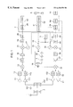
- FIG. 1 is a schematic block diagram for indicating an arrangement of a multi-band radio terminal apparatus according to a first embodiment of the present invention.
- This first embodiment corresponds to a CDMA type radio (wireless) terminal apparatus designed for U.S.A.
- This CDMA type radio terminal apparatus uses an 800 MHz band (TIA/EIA1S-95-A, namely 800 MHz-band cellular system) as the first frequency band, and a 1.9 GHz band (ANSI J-STD-008, 1.9 GHz-band PCS system) as the second frequency band.
- 800 MHz band TIA/EIA1S-95-A, namely 800 MHz-band cellular system
- a 1.9 GHz band ANSI J-STD-008, 1.9 GHz-band PCS system
- a radio (wireless) communication signal transmitted from a base station is received by a first frequency band antenna 1 , and then a signal within a reception frequency (all channels) band is derived from a first frequency band duplexer 2 .
- the reception frequency band of the reception signal within the first frequency band, derived from the first frequency band duplexer 2 is selected from 869.01 MHz to 894 MHz.
- the reception signal is amplified by a first frequency band low-noise amplifier 11 , and an unnecessary signal component is removed from the amplified reception signal by a first frequency band RX band-pass filter 12 .
- the resultant reception signal is converted into a reception intermediate frequency signal (210.38 MHz) by a first frequency band RX mixer 13 .
- the signal band of this reception intermediate frequency signal is limited to 1.25 MHz by using an RX IF band-pass filter 17 , and thereafter the limited reception-IF signal is amplified by an RX variable gain amplifier 18 so as to obtain a necessary signal level there of in the post-staged circuit. Then, the amplified IF signal is 4-phase-demodulated by an RX second mixer 21 of a base-band analog signal processing circuit 7 . Moreover, the frequency band of this reception base-band signal is limited by an RX low-pass filter 24 , and then the band-limited reception base-band signal is converted into a reception digital signal by an analog-to-digital converter 25 . This digital signal is entered into a CDMA demodulator 26 of a base-band digital signal processing circuit 7 provided at a post stage of the A/D converter 25 .
- the CDMA demodulator 26 demodulates such a reception digital signal which has been processed by way of the convolution coding, the block interleaving, the 64-order quadrature modulating, and the direct sequence spreading.
- a Viterbi decoder 53 is employed to decode the convolution code.
- a signal which is decoded when the reception digital signal is demodulated by the CDMA demodulator 26 is constituted by a control signal and a reception voice (speech) signal.
- This reception voice signal is processed by a vocoder 51 so as to decode a high-efficiency voice code, and a PCM code is decoded by a codec 52 in order to be outputted as a voice signal from a receiver 8 .
- the control signal is supplied to a controller 54 , and this controller 54 discriminates the control signal to execute various sorts of control operations of the radio terminal apparatus.
- transmission voice is picked up by a microphone 9 , the voice signal is PCM-coded by the codes 52 , and then the PCM-coded voice signal is processed by the vocoder 51 by way of the high efficiency speech coding to produce a transmission voice signal.
- This transmission voice signal and the control signal produced by the controller 54 are processed by the CDMA modulator 46 by way of the convolution coding, the block interleaving, the 64-order quadrature modulating, and the direct sequence spreading, so that a transmission digital signal. Then, this transmission digital signal is supplied to a TX digital-to-analog converter 45 of a base-band analog signal processing circuit 6 provided at the next stage of the CDMA modulator 46 .
- the TX D/A converter 45 D/A-converts this transmission digital signal into a transmission baseband signal, and then the bandwidth of this transmission base-band signal is limited by a TX low-pass filter 44 . Furthermore, this transmission base-band signal is 4-phase-modulated by a TX second mixer 41 so as to be converted into a TX intermediate frequency signal (255.38 MHz). The bandwidth of this TX intermediate frequency signal is limited to 1.25 MHz by a TX IF band-pass filter 38 .
- the band-limited TX IF signal is amplified by a TX variable amplifier 37 provided at a post stage to a necessary signal level thereof.
- This transmission IF signal is converted into a transmission signal by a first frequency band TX mixer 33 , an unnecessary signal component is removed from this transmission IF signal by a first frequency band TX band-pass filter 32 , and then the resultant transmission signal is amplified by a first frequency band power amplifier 31 .
- the transmission frequency band of the first frequency transmission signal is selected to be 824.01 MHz to 849 MHz.
- signals outside the transmission frequency (all channels) band are removed by the first frequency duplexer 2 , and then a radio (wireless) communication signal is radiated from the first frequency band antenna 1 .
- a radio (wire-less) communication signal transmitted from a base station is received by a second frequency band antenna 101 , and then a signal within a reception frequency (all channels) band is derived from a second frequency band duplexer 102 .
- the reception frequency band of the reception signal within the second frequency band, derived from the second frequency band duplexer 102 is selected from 1930 MHz to 1990 MHz.
- the reception signal is amplified by a second frequency band low-noise amplifier 111 , and an unnecessary signal component is removed from the amplified reception signal by a second frequency band RX band-pass filter 112 .
- the resultant reception signal is converted into a reception intermediate frequency signal (210.38 MHz) by a second frequency band RX mixer 113 .
- the subsequent signal process operations are similar to those of the first communication frequency band.
- signal process operations capable of deriving a transmission intermediate signal (290.38 MHz) in this second frequency band are similar to those of the first frequency band. However, this transmission intermediate frequency of the second frequency band is different from that of the first frequency band.
- This transmission IF signal is converted into a transmission signal by the first frequency band TX mixer 33 , an unnecessary signal component of this transmission IF signal is removed by a second frequency band TX band-pass filter 132 , and then the resultant transmission signal is amplified by a second frequency band power amplifier 131 .
- the transmission frequency band of the second frequency transmission signal is selected to be 1850 MHz to 1910 MHz.
- signals outside the transmission frequency (all channels) band are removed by the second frequency duplexer 102 , and then a radio (wire-less) communication signal is radiated from the second frequency band antenna 101 .
- a microcomputer is provided as a main control unit. As indicated by a dotted line of FIG. 1, this controller 54 controls the gain of the RX variable gain amplifier 18 in order that a frequency of a phase-locked loop (PLL) is properly set, and also a level of a reception signal becomes a proper level. The controller 54 controls the gain of the TX variable gain amplifier 37 in order that a level of a transmissions signal becomes a proper level. Also, this controller 54 performs control operations of the respective circuit units.
- PLL phase-locked loop
- the controller 54 is connected to a man-to-machine interface 10 constituted of a sounder, a liquid crystal display (LCD) device, and a keypad so as to execute a calling process operation when a telephone call is received, and a dialing process operation when a telephone call is issued.
- a man-to-machine interface 10 constituted of a sounder, a liquid crystal display (LCD) device, and a keypad so as to execute a calling process operation when a telephone call is received, and a dialing process operation when a telephone call is issued.
- a local oscillator (LO) system there are provided a first frequency converting system, and a second frequency converting system.
- the first frequency converting system converts a radio frequency signal into an intermediate frequency signal, and/or converts an intermediate frequency signal into a radio frequency signal.
- the second frequency converting system 4-phase-modulates/demodulates both an intermediate frequency signal and a base-band signal.
- a local oscillator used in the respective frequency converting operations is arranged by a voltage-controlled oscillator and a PLL (phase-locked loop).
- the RX (reception side) intermediate frequency is commonly set to 210.38 MHz in both the communication frequency bands, whereas the TX (transmission side) intermediate frequencies are set to 255.38 MHz (first communication frequency band) and 290.38 MHz (second communication frequency band).
- the first frequency converting system is constituted by the first frequency band RX mixer 13 , the first frequency TX mixer 33 , the first voltage-controlled oscillator 15 , the first phase-locked loop 16 , an LO doubler 20 , an LO band-pass filter 3 , and a first local oscillator switch 19 .
- the second frequency converting system is arranged by the second frequency band RX mixer 21 , the second RX local oscillator 27 , the second frequency band TX mixer 41 , the second voltage-controlled oscillator 35 , and the second phase-locked loop 36 . Both the first phase-locked loop and the second phase-locked loop are arranged in such a manner that a temperature-compensated crystal oscillator 5 is employed as a reference oscillator source, and a local oscillator frequency is controlled by the controller 54 .
- the activated circuits are changed by such a condition that this radio terminal apparatus is operated in any of the communication frequency bands.
- the first local oscillator switch 19 is switched to the output side of the first voltage-controlled oscillator 15 , and a first local oscillator is constituted by the first voltage-controlled oscillator 15 and the first phase-locked loop 16 so as to output a first local oscillator signal.
- the first frequency band RX mixer 13 uses the above-explained first local oscillator signal in order to convert the reception signal (869.01 MHz to 894 MHz) into the reception intermediate frequency signal (210.38 MHz).
- the first local oscillator signal any one of an upper side wave and a lower side wave may be selected.
- the frequency thereof is selected to be 1079.39 MHz to 1104.38 MHz.
- the first frequency band TX mixer 33 uses the same first local oscillator signal (1079.39 MHz to 1104.38 MHz) so as to convert the transmission intermediate frequency (255.38 MHz) into the transmission signal (824.01 MHz to 849 MHz).
- the transmission intermediate frequency since the transmission frequency is determined, the transmission intermediate frequency may be determined based upon both this transmission frequency and the first local oscillator frequency.
- the first local oscillator switch 19 is switched to the output side of the LO band-pass filter 3 , and a first local oscillator is constituted by the first voltage-controlled oscillator 15 and the local oscillator frequency thereof is doubled by the LO doubler 20 . Then, an unnecessary signal wave of the doubled local oscillator signal is removed by the local oscillator band-pass filter 3 so as to output as the first local oscillator signal.
- the first frequency band RX mixer 13 uses the above-explained first local oscillator signal in order to convert the reception signal (1930 MHz to 1990 MHz) into the reception intermediate frequency signal (210.38 MHz).
- the first local oscillator signal any one of an upper side wave and a lower side wave may also be selected.
- the frequency thereof is selected to be 2140.38 MHz to 2200.38 MHz.
- an oscillator frequency of an oscillator namely, first voltage-controlled oscillator 15 and first phase-locked loop 16
- the first frequency band TX mixer 33 uses the same first local oscillator signal (2140.38 MHz to 2200.38 MHz) so as to convert the transmission intermediate frequency (290.38 MHz) into the transmission signal (1850 MHz to 1910 MHz).
- the transmission intermediate frequency since the transmission frequency is determined, the transmission intermediate frequency may be determined based upon both this transmission frequency and the first local oscillator frequency.
- both the first voltage-controlled oscillator 15 and the first phase-locked loop 16 may cover the oscillator frequency range defined from 1070.19 MHz to 1104.38 MHz.
- the same means of the radio terminal apparatus may function in any of such cases that this radio terminal apparatus is operated in the first communication frequency band, and also in the second communication frequency band.
- the frequency of the reception intermediate signal when the radio terminal apparatus is operated in the first communication frequency band is identical to that when the radio terminal apparatus is operated in the second communication frequency band.
- a local oscillator signal having a frequency of 210.38 MHz is produced by the second RX local oscillator 27 , and this local oscillator signal is supplied to the second RX frequency mixer 21 for the 4-phase modulation purpose.
- the frequency of the transmission intermediate signal when the radio terminal apparatus is operated in the first communication frequency band is different from that when the radio terminal apparatus is operated in the second communication frequency band.
- a second TX local oscillator is arranged by the second voltage-controlled oscillator 35 and the second phase-locked loop 36 , when the radio terminal apparatus is operated in the first communication frequency band, such a local oscillator signal having a frequency of 255.38 MHz is produced, whereas when the radio terminal apparatus is operated in the second communication band, such a local oscillator signal having a frequency of 290.38 MHz is produced.
- These local oscillator signals are supplied to the second TX frequency mixer 41 .
- the local oscillator arranged by employing the second voltage-controlled oscillator 35 and the second phase-locked loop 36 may be operated by switching the oscillator frequencies between 255.38 MHz and 290.38 MHz.
- the pass bands of the TX intermediate frequency band-pass filter 38 are selected to be 255.38 MHz and 290.38 MHz. Since this band-pass filter 38 merely can pass the frequency of the TX IF signal and can have a sufficiently large attenuation amount as to the frequency of the RX IF signal, this band-pass filter 38 may be replaced by a high-pass filter having a simple structure.
- the first frequency converting system for converting the radio frequency into the intermediate frequency may be realized by employing such a relatively simpler circuit arrangement that a single local oscillator is commonly used in the two communication frequency bands, and also both the mixers 13 and 33 are commonly used.
- This single local oscillator is constituted by the voltage-controlled oscillator 15 controlled by the phase-locked loop 16 , the frequency doubler 20 , the local oscillator band-pass filter 3 , and also one local oscillator switch 19 .
- this local oscillator frequency is different from the communication frequency, there is no risk that the local oscillating operation is brought into unstable condition due to mutual interference.
- FIG. 2 is a schematic block diagram for showing an arrangement of a multi-band radio (wire-less) terminal apparatus according to a second embodiment of the present invention.
- this second embodiment owns a different structure of a first frequency converting system.
- the first frequency converting system employed in the second embodiment is constructed as follows.
- a first local oscillator switch 19 is switched to an output side of a local oscillator band-pass filter 3 , and a first local oscillator is arranged by a first voltage-controlled oscillator 15 and a first phase-locked loop 16 .
- the local oscillating frequency of this first local oscillator is frequency-divided by a local oscillator frequency divider 40 , and then an unnecessary signal wave of the divided local oscillator signal is removed by a local oscillator band-pass filter 3 , so that the resultant local oscillator signal is outputted as a first local oscillator signal.
- the first local oscillator switch 19 is switched to an oscillator output side of the first voltage-controlled oscillator 15 , and a first local oscillator signal is outputted from the first local oscillator which is constructed by the first voltage-controlled oscillator 15 and the first phase-locked loop 16 .
- both the first voltage-controlled oscillator 15 and the first phase-locked loop 16 may cover such an oscillating frequency range defined from 2140.38 MHz to 2208.76 MHz.
- FIG. 3 is a schematic block diagram for representing an arrangement of a multi-band radio terminal apparatus according to a third embodiment of the present invention.
- This third embodiment corresponds to a CDMA type multi-band radio terminal apparatus which uses the U.S. 800 MHz band (TIA/EIA IS-95-A, namely 800 MHz band cellular system) as a first communication frequency band, and also uses the Japanese 800 MHz band (ARIB STDT53, namely CDMA automobile portable telephone system) as a second communication frequency band.
- U.S. 800 MHz band TIA/EIA IS-95-A, namely 800 MHz band cellular system
- ARIB STDT53 namely CDMA automobile portable telephone system
- This third embodiment owns features as follows. That is, although the frequency allocations are different, the multi-band radio terminal apparatus may be commonly operated as the CDMA type multi-band radio terminal apparatus. Accordingly, the operations of this multi-band radio terminal apparatus in any of the first and second communication frequency bands are similar to those of the first embodiment.
- a high frequency front-end unit may be commonly employed for the first communication frequency band and the second communication frequency band, but need not be employed only for each of the first and second communication frequency bands, which is different from the first embodiment.
- This high frequency front-end unit is arranged by the antenna, the duplexer, the low noise amplifier, the RX band-pass filter, the power amplifier, and the TX band-pass filter.
- a first frequency converting system of this multi-band radio terminal apparatus is realized as follows.
- this radio terminal apparatus is operated in the first communication frequency band, and also in the second communication frequency band, the same means may function, and further both a first voltage-controlled oscillator 15 and a first phase-locked loop 16 constitute a first local oscillator so as to output a first local oscillator signal.
- a frequency of a reception intermediate frequency signal is selected to be 210.38 MHz
- an oscillator frequency of the first local oscillator is selected to be 658.63 MHz through 683.62 MHz.
- an oscillator frequency of the first local oscillator (arranged by first voltage-controlled oscillator 15 and first phase-locked loop 16 ) is selected to be 621.62 MHz to 659.62 MHz.
- any one of an upper side wave and a lower side wave may be selected as the first local oscillator signal, the lower side wave is employed in this third embodiment.
- the first local oscillator (constituted by first voltage-controlled oscillator 15 and first phase-locked loop 16 ) may cover such an oscillating frequency range defined between 621.62 MHz and 693.92 MHz.
- a frequency of a transmission intermediate frequency signal is equal to 165.38 MHz in the case that this multi-band radio terminal apparatus is operated in the first communication frequency band, and further is equal to 265.38 MHz in the case that this multi-band radio terminal apparatus is operated in the second communication frequency band.
- a structure of the second frequency converting system on the signal reception (RX) side is similar to that of the first embodiment.
- a structure of the second frequency converting system on the signal transmission (TX) side is given as follows. There is a large separation between the required second local oscillator frequencies, respectively, when the multi-band radio terminal apparatus is operated in the first communication frequency band, and also in the second communication frequency band. Accordingly, two sets of second TX local oscillators are provided, namely a first TX second local oscillator 47 and a second TX second local oscillator 48 . When the multi-band radio terminal apparatus is operated in the first communication frequency band, the first TX second local oscillator 47 produces a local oscillator signal (165.38 MHz).
- the second TX second local oscillator 48 When the multi-band radio terminal apparatus is operated in the second communication frequency band, the second TX second local oscillator 48 produces a local oscillator signal (265.38 MHz). These local oscillator signals are selectively switched by a second local oscillator switch 49 to be supplied to the TX second frequency mixer 41 for the 4-phase modulating operation.
- a TX intermediate frequency blocking filter 39 is applied to the multi-band radio terminal apparatus. While the blocking frequency band of this filter 39 is set to the reception intermediate frequency band (210.38 MHz), such signals within the transmission intermediate frequency band (165.38 MHz and 265.38 MHz) may pass through this filter 39 .
- the high frequency front-end unit may be commonly employed for the first communication frequency band and the second communication frequency band, but need not be employed only for each of the first and second communication frequency bands.
- This high frequency front-end unit is arranged by the antenna, the duplexer, the low noise amplifier, the RX band-pass filter, the power amplifier, and the TX band-pass filter.
- the first frequency converting system of this multi-band radio terminal apparatus can directly use the local oscillator signal of the local oscillator arranged by the first voltage-controlled oscillator 15 and the phase-locked loop 16 .
- the arrangement of the first frequency converting system can be made simple.
- this local oscillator frequency is different from the communication signal frequency, there is no such a risk that the local oscillating operation is brought into unstable condition due to mutual interference.
- the various embodiments of the CDMA type multi-band radio terminal apparatus have been described.
- the present invention is not limited to the above embodiments, but may be apparently applied to other types of communication systems.
- the above-explained structural means of the multi-band radio terminal apparatus are not limitedly described in the respective embodiments. Alternatively, other structural means may be employed.
Abstract
Description
Claims (2)
Priority Applications (5)
| Application Number | Priority Date | Filing Date | Title |
|---|---|---|---|
| US09/886,992 US6850739B2 (en) | 1998-03-04 | 2001-06-25 | Multi-band radio terminal apparatus |
| US10/094,710 US6587673B2 (en) | 1998-03-04 | 2002-03-12 | Multi-band radio terminal apparatus |
| US10/256,073 US6725019B2 (en) | 1998-03-04 | 2002-09-27 | Multi-band radio terminal apparatus |
| US10/435,557 US6882830B2 (en) | 1998-03-04 | 2003-05-12 | Multi-band radio terminal apparatus |
| US11/057,213 US20050148361A1 (en) | 1998-03-04 | 2005-02-15 | Multi-band radio terminal apparatus |
Applications Claiming Priority (2)
| Application Number | Priority Date | Filing Date | Title |
|---|---|---|---|
| JP05230998A JP3898830B2 (en) | 1998-03-04 | 1998-03-04 | Multiband wireless terminal device |
| JP10-052309 | 1998-03-04 |
Related Child Applications (2)
| Application Number | Title | Priority Date | Filing Date |
|---|---|---|---|
| US09/886,992 Continuation US6850739B2 (en) | 1998-03-04 | 2001-06-25 | Multi-band radio terminal apparatus |
| US10/094,710 Continuation US6587673B2 (en) | 1998-03-04 | 2002-03-12 | Multi-band radio terminal apparatus |
Publications (1)
| Publication Number | Publication Date |
|---|---|
| US6438358B1 true US6438358B1 (en) | 2002-08-20 |
Family
ID=12911194
Family Applications (6)
| Application Number | Title | Priority Date | Filing Date |
|---|---|---|---|
| US09/261,179 Expired - Fee Related US6438358B1 (en) | 1998-03-04 | 1999-03-03 | Multi-band radio terminal apparatus |
| US09/886,992 Expired - Lifetime US6850739B2 (en) | 1998-03-04 | 2001-06-25 | Multi-band radio terminal apparatus |
| US10/094,710 Expired - Lifetime US6587673B2 (en) | 1998-03-04 | 2002-03-12 | Multi-band radio terminal apparatus |
| US10/256,073 Expired - Fee Related US6725019B2 (en) | 1998-03-04 | 2002-09-27 | Multi-band radio terminal apparatus |
| US10/435,557 Expired - Fee Related US6882830B2 (en) | 1998-03-04 | 2003-05-12 | Multi-band radio terminal apparatus |
| US11/057,213 Abandoned US20050148361A1 (en) | 1998-03-04 | 2005-02-15 | Multi-band radio terminal apparatus |
Family Applications After (5)
| Application Number | Title | Priority Date | Filing Date |
|---|---|---|---|
| US09/886,992 Expired - Lifetime US6850739B2 (en) | 1998-03-04 | 2001-06-25 | Multi-band radio terminal apparatus |
| US10/094,710 Expired - Lifetime US6587673B2 (en) | 1998-03-04 | 2002-03-12 | Multi-band radio terminal apparatus |
| US10/256,073 Expired - Fee Related US6725019B2 (en) | 1998-03-04 | 2002-09-27 | Multi-band radio terminal apparatus |
| US10/435,557 Expired - Fee Related US6882830B2 (en) | 1998-03-04 | 2003-05-12 | Multi-band radio terminal apparatus |
| US11/057,213 Abandoned US20050148361A1 (en) | 1998-03-04 | 2005-02-15 | Multi-band radio terminal apparatus |
Country Status (2)
| Country | Link |
|---|---|
| US (6) | US6438358B1 (en) |
| JP (1) | JP3898830B2 (en) |
Cited By (20)
| Publication number | Priority date | Publication date | Assignee | Title |
|---|---|---|---|---|
| US20010036838A1 (en) * | 1998-03-04 | 2001-11-01 | Kazutoshi Higuchi | Multi-band radio terminal apparatus |
| US20010051869A1 (en) * | 2000-06-09 | 2001-12-13 | Samsung Electronics Co., Ltd. | Method for operating a voice function in a dual-mode radio mobile terminal |
| US20020000890A1 (en) * | 2000-06-30 | 2002-01-03 | Matsushita Electric Industrial Co., Ltd. | Radio communications apparatus |
| US20020051441A1 (en) * | 2000-10-31 | 2002-05-02 | Hynix Semiconductor, Inc. | Voltage offset compensating device of CDMA communication system transmitter |
| US20030022652A1 (en) * | 2001-06-14 | 2003-01-30 | Honeywell Federal Manufacturing & Technologies, Llc | ISM band to U-NII band frequency transverter and method of frequency transversion |
| US20030114130A1 (en) * | 2001-02-26 | 2003-06-19 | Hideki Morishige | Frequency converter and communication device |
| US20040043727A1 (en) * | 2001-06-12 | 2004-03-04 | Naotaka Sato | Multi-band mobile communication device |
| US20040087279A1 (en) * | 2001-03-26 | 2004-05-06 | Claus Muschallik | Transmitting and receiving unit |
| US20040092281A1 (en) * | 2002-10-24 | 2004-05-13 | Bbnt Solutions Llc | Spectrum-adaptive networking |
| US20040152484A1 (en) * | 2001-08-07 | 2004-08-05 | Pratt Stephen J. | Multi-band tranceivers with reduced frequency sources for digital transmissions |
| US20040152424A1 (en) * | 2001-01-12 | 2004-08-05 | Yongnan Xuan | Method of receiving and transmitting the signal of high frequency |
| US20040157568A1 (en) * | 2001-07-27 | 2004-08-12 | Michael Asam | Circuit arrangement for the regulation of a direct component of a signal and mobile radio transmitter |
| US20040192316A1 (en) * | 2001-01-30 | 2004-09-30 | Ulrich Botzel | Frequency scheme for data transmission systems |
| US20040204036A1 (en) * | 2002-11-05 | 2004-10-14 | Fodus Communications, Inc. | Configurable multi-band RF transceiver with a cascaded frequency conversion scheme |
| US20040259518A1 (en) * | 2001-07-18 | 2004-12-23 | Adem Aktas | Multi standard transceiver architecture for wlan |
| US20050190735A1 (en) * | 2004-02-27 | 2005-09-01 | Yusuke Shinoda | Mobile terminal |
| US7013121B1 (en) * | 2000-02-18 | 2006-03-14 | Telaxis Communications Corporation | Frequency conversion circuit using common local synthesizer |
| US20060055445A1 (en) * | 2002-07-24 | 2006-03-16 | Sirific Wireless Corporation | Multi-standard amplifier |
| US20070280185A1 (en) * | 2002-05-03 | 2007-12-06 | Atheros Communications, Inc. | Dual Frequency Band Wireless LAN |
| CN101356739B (en) * | 2006-01-12 | 2012-08-08 | 索尼爱立信移动通讯股份有限公司 | Multiband antenna switch |
Families Citing this family (39)
| Publication number | Priority date | Publication date | Assignee | Title |
|---|---|---|---|---|
| DE19916574C1 (en) * | 1999-04-13 | 2001-01-18 | Siemens Ag | Frequency processing system for a mobile radio dual band transmitter / receiver (transceiver) |
| US6925067B2 (en) | 1999-04-23 | 2005-08-02 | Qualcomm, Incorporated | Configuration of overhead channels in a mixed bandwidth system |
| KR100363796B1 (en) * | 2000-04-20 | 2002-12-11 | 엘디케이전자 주식회사 | Wireless transceiver using a three multiplier |
| US20020137469A1 (en) * | 2000-07-24 | 2002-09-26 | Manabu Yamaguchi | Radio communication apparatus and radio communication method |
| JP3882524B2 (en) * | 2001-04-06 | 2007-02-21 | 松下電器産業株式会社 | Broadband tuner |
| US6865376B2 (en) * | 2001-07-03 | 2005-03-08 | Kyocera Wireless Corp. | System and method for a GPS enabled antenna |
| KR100828758B1 (en) * | 2001-09-19 | 2008-05-09 | 지멘스 악티엔게젤샤프트 | Multiband receiver and it's receiving method |
| US7359684B2 (en) * | 2001-11-06 | 2008-04-15 | Texas Instruments Incorporated | Wireless communication system with variable intermediate frequency transmitter |
| US7141817B2 (en) * | 2001-11-30 | 2006-11-28 | Semiconductor Energy Laboratory Co., Ltd. | Light emitting device |
| US6968204B2 (en) * | 2001-12-28 | 2005-11-22 | Visteon Global Technologies, Inc. | Narrow band and spread spectrum communication system for a vehicle |
| US6512472B1 (en) * | 2002-01-15 | 2003-01-28 | Motorola, Inc. | Method and apparatus for optimizing dynamic range of a wideband analog-to-digital converter |
| US7064608B2 (en) * | 2002-11-26 | 2006-06-20 | Scriptl, Llc | Feed-forward-back suppressed noise circuits |
| EP1616392A2 (en) * | 2003-02-28 | 2006-01-18 | Motorola, Inc. | System and method for transmitting ultrawide bandwidth signals |
| JP4168786B2 (en) | 2003-03-05 | 2008-10-22 | 日本電気株式会社 | Multiband radio terminal, band switching method used therefor, and program therefor |
| US7376440B2 (en) * | 2003-04-16 | 2008-05-20 | Kyocera Wireless Corp. | N-plexer systems and methods for use in a wireless communications device |
| CN100379157C (en) * | 2003-06-24 | 2008-04-02 | 松下电器产业株式会社 | High frequency receiving device, integrated circuit used for same, and TV receiver using them |
| US7043097B2 (en) * | 2003-07-25 | 2006-05-09 | Agility Communications, Inc. | Traveling-wave optoelectronic wavelength converter |
| JP4536528B2 (en) * | 2004-01-23 | 2010-09-01 | パナソニック株式会社 | Low noise bias circuit for differential and differential signal processing device |
| US20050208964A1 (en) * | 2004-03-18 | 2005-09-22 | Earls Jeffrey D | Use of a preselection filter bank and switched local oscillator counter in an instrumentation receiver |
| JP4487695B2 (en) | 2004-09-07 | 2010-06-23 | 日本電気株式会社 | Multiband radio |
| KR100690358B1 (en) | 2004-12-28 | 2007-03-09 | 전자부품연구원 | The local Oscillator for a dual band repeater |
| KR100692300B1 (en) * | 2005-08-13 | 2007-03-09 | 인티그런트 테크놀로지즈(주) | Terrestrial-Digital Multimedia Broadcasting and Digital Audio Broadcasting Low-IF Receiver. |
| KR100726782B1 (en) * | 2005-08-22 | 2007-06-11 | 인티그런트 테크놀로지즈(주) | Terrestrial-Digital Multimedia Broadcasting and Digital Audio Broadcasting Low-IF Receiver. |
| KR100726785B1 (en) * | 2005-08-17 | 2007-06-11 | 인티그런트 테크놀로지즈(주) | Terrestrial-Digital Multimedia Broadcasting and Digital Audio Broadcasting Low-IF Receiver. |
| JP4571591B2 (en) * | 2006-01-25 | 2010-10-27 | 旭化成エレクトロニクス株式会社 | Wireless communication circuit |
| JP4730840B2 (en) * | 2006-11-15 | 2011-07-20 | ルネサスエレクトロニクス株式会社 | Semiconductor integrated circuit for communication and radio communication terminal device using the same |
| KR100838521B1 (en) * | 2006-12-05 | 2008-06-17 | 전자부품연구원 | Digital intermediate frequency transmitter for wireless communication |
| TWI407761B (en) * | 2006-12-07 | 2013-09-01 | Wistron Neweb Corp | Communication device capable of operating in a plurality of communications systems |
| US7729656B2 (en) * | 2007-01-03 | 2010-06-01 | Wilson Electronics | Cellular network low noise amplifiers for use with multiple frequencies |
| US7733698B2 (en) * | 2007-03-21 | 2010-06-08 | Qimonda Ag | Memory device, a non-volatile semiconductor memory device and a method of forming a memory device |
| US7945217B2 (en) * | 2007-11-13 | 2011-05-17 | Provigent Ltd. | Multi-mode baseband-IF converter |
| US7991368B2 (en) * | 2007-12-27 | 2011-08-02 | Provigent Ltd | Integrated RF-IF converter |
| WO2010000336A1 (en) * | 2008-07-04 | 2010-01-07 | Siemens Aktiengesellschaft | Dual band radio communication using a common oscillator |
| WO2010054263A2 (en) * | 2008-11-07 | 2010-05-14 | Viasat, Inc. | Dual conversion transmitter with single local oscillator |
| US9077393B2 (en) | 2010-08-30 | 2015-07-07 | Samsung Electronics Co., Ltd. | Apparatus and method for a multi-band radio operating in a wireless network |
| TWI681642B (en) * | 2018-07-25 | 2020-01-01 | 瑞昱半導體股份有限公司 | Dual-mode wireless transceiver |
| CN114448460B (en) * | 2020-10-16 | 2023-03-24 | 华为技术有限公司 | Radio frequency system, equipment and control method |
| US20230095660A1 (en) * | 2021-09-24 | 2023-03-30 | Hughes Network Systems, Llc | Mobile tactical radio device, system and method |
| US11677436B1 (en) * | 2021-12-01 | 2023-06-13 | Rockwell Collins, Inc. | Antenna optimization for SATCOM waveforms |
Citations (5)
| Publication number | Priority date | Publication date | Assignee | Title |
|---|---|---|---|---|
| US5794159A (en) * | 1996-08-07 | 1998-08-11 | Nokia Mobile Phones Limited | Dual band mobile station employing cross-connected transmitter and receiver circuits |
| US5852784A (en) * | 1996-04-08 | 1998-12-22 | Matsushita Electric Industrial Co., Ltd. | Multiband mobile unit communication apparatus |
| US6014571A (en) * | 1996-06-10 | 2000-01-11 | Matsushita Electric Industrial Co., Ltd. | Multiband mobile unit communication apparatus |
| US6029052A (en) * | 1997-07-01 | 2000-02-22 | Telefonaktiebolaget Lm Ericsson | Multiple-mode direct conversion receiver |
| US6175746B1 (en) * | 1996-04-08 | 2001-01-16 | Matsushita Electric Industrial Co., Ltd. | Multiband mobile unit communication apparatus |
Family Cites Families (3)
| Publication number | Priority date | Publication date | Assignee | Title |
|---|---|---|---|---|
| GB2310342A (en) * | 1996-02-16 | 1997-08-20 | Northern Telecom Ltd | Dual mode radio transceiver front end |
| US6308048B1 (en) * | 1997-11-19 | 2001-10-23 | Ericsson Inc. | Simplified reference frequency distribution in a mobile phone |
| JP3898830B2 (en) * | 1998-03-04 | 2007-03-28 | 株式会社日立製作所 | Multiband wireless terminal device |
-
1998
- 1998-03-04 JP JP05230998A patent/JP3898830B2/en not_active Expired - Fee Related
-
1999
- 1999-03-03 US US09/261,179 patent/US6438358B1/en not_active Expired - Fee Related
-
2001
- 2001-06-25 US US09/886,992 patent/US6850739B2/en not_active Expired - Lifetime
-
2002
- 2002-03-12 US US10/094,710 patent/US6587673B2/en not_active Expired - Lifetime
- 2002-09-27 US US10/256,073 patent/US6725019B2/en not_active Expired - Fee Related
-
2003
- 2003-05-12 US US10/435,557 patent/US6882830B2/en not_active Expired - Fee Related
-
2005
- 2005-02-15 US US11/057,213 patent/US20050148361A1/en not_active Abandoned
Patent Citations (5)
| Publication number | Priority date | Publication date | Assignee | Title |
|---|---|---|---|---|
| US5852784A (en) * | 1996-04-08 | 1998-12-22 | Matsushita Electric Industrial Co., Ltd. | Multiband mobile unit communication apparatus |
| US6175746B1 (en) * | 1996-04-08 | 2001-01-16 | Matsushita Electric Industrial Co., Ltd. | Multiband mobile unit communication apparatus |
| US6014571A (en) * | 1996-06-10 | 2000-01-11 | Matsushita Electric Industrial Co., Ltd. | Multiband mobile unit communication apparatus |
| US5794159A (en) * | 1996-08-07 | 1998-08-11 | Nokia Mobile Phones Limited | Dual band mobile station employing cross-connected transmitter and receiver circuits |
| US6029052A (en) * | 1997-07-01 | 2000-02-22 | Telefonaktiebolaget Lm Ericsson | Multiple-mode direct conversion receiver |
Cited By (44)
| Publication number | Priority date | Publication date | Assignee | Title |
|---|---|---|---|---|
| US6725019B2 (en) | 1998-03-04 | 2004-04-20 | Hitachi, Ltd. | Multi-band radio terminal apparatus |
| US6850739B2 (en) * | 1998-03-04 | 2005-02-01 | Hitachi, Ltd. | Multi-band radio terminal apparatus |
| US6882830B2 (en) | 1998-03-04 | 2005-04-19 | Hitachi, Ltd. | Multi-band radio terminal apparatus |
| US20010036838A1 (en) * | 1998-03-04 | 2001-11-01 | Kazutoshi Higuchi | Multi-band radio terminal apparatus |
| US20050148361A1 (en) * | 1998-03-04 | 2005-07-07 | Kazutoshi Higuchi | Multi-band radio terminal apparatus |
| US6587673B2 (en) * | 1998-03-04 | 2003-07-01 | Hitachi, Ltd. | Multi-band radio terminal apparatus |
| US20030199261A1 (en) * | 1998-03-04 | 2003-10-23 | Kazutoshi Higuchi | Multi-band radio terminal apparatus |
| US7013121B1 (en) * | 2000-02-18 | 2006-03-14 | Telaxis Communications Corporation | Frequency conversion circuit using common local synthesizer |
| US7107208B2 (en) * | 2000-06-09 | 2006-09-12 | Samsung Electronics Co., Ltd. | Dual mode radio mobile terminal in which an analog or digital mode is determined by request of a voice function |
| US20010051869A1 (en) * | 2000-06-09 | 2001-12-13 | Samsung Electronics Co., Ltd. | Method for operating a voice function in a dual-mode radio mobile terminal |
| US20020000890A1 (en) * | 2000-06-30 | 2002-01-03 | Matsushita Electric Industrial Co., Ltd. | Radio communications apparatus |
| US6973136B2 (en) * | 2000-06-30 | 2005-12-06 | Matsushita Electric Industrial Co., Ltd. | Radio communications apparatus |
| US20020051441A1 (en) * | 2000-10-31 | 2002-05-02 | Hynix Semiconductor, Inc. | Voltage offset compensating device of CDMA communication system transmitter |
| US7383025B2 (en) * | 2001-01-12 | 2008-06-03 | Yongnan Xuan | Method for processing RF signals for receiving and transmission |
| US20040152424A1 (en) * | 2001-01-12 | 2004-08-05 | Yongnan Xuan | Method of receiving and transmitting the signal of high frequency |
| US7016683B2 (en) * | 2001-01-30 | 2006-03-21 | Infineon Technologies Ag | Frequency scheme for data transmission systems |
| US20040192316A1 (en) * | 2001-01-30 | 2004-09-30 | Ulrich Botzel | Frequency scheme for data transmission systems |
| US20030114130A1 (en) * | 2001-02-26 | 2003-06-19 | Hideki Morishige | Frequency converter and communication device |
| US6968159B2 (en) * | 2001-02-26 | 2005-11-22 | Mitsubishi Denki Kabushiki Kaisha | Frequency converter and communication device |
| US7203466B2 (en) | 2001-03-26 | 2007-04-10 | Infineon Technologies Ag | Transmitting and receiving unit |
| US20040087279A1 (en) * | 2001-03-26 | 2004-05-06 | Claus Muschallik | Transmitting and receiving unit |
| US20040043727A1 (en) * | 2001-06-12 | 2004-03-04 | Naotaka Sato | Multi-band mobile communication device |
| US20080182617A1 (en) * | 2001-06-12 | 2008-07-31 | Naotaka Sato | Multiband mobile communication apparatus |
| US7386278B2 (en) * | 2001-06-12 | 2008-06-10 | Sony Corporation | Multi-band mobile communication device |
| US7024165B2 (en) * | 2001-06-14 | 2006-04-04 | Honeywell Federal Manufacturing & Technologies, Llc | ISM band to U-NII band frequency transverter and method of frequency transversion |
| US20050255821A1 (en) * | 2001-06-14 | 2005-11-17 | Stepp Jeffrey D | ISM band to U-NII band frequency transverter and method of frequency transversion |
| US20030022652A1 (en) * | 2001-06-14 | 2003-01-30 | Honeywell Federal Manufacturing & Technologies, Llc | ISM band to U-NII band frequency transverter and method of frequency transversion |
| US7107015B2 (en) | 2001-06-14 | 2006-09-12 | Honeywell Federal Manufacturing & Technologies, Llc | ISM band to U-NII band frequency transverter and method of frequency transversion |
| US20040259518A1 (en) * | 2001-07-18 | 2004-12-23 | Adem Aktas | Multi standard transceiver architecture for wlan |
| US20040157568A1 (en) * | 2001-07-27 | 2004-08-12 | Michael Asam | Circuit arrangement for the regulation of a direct component of a signal and mobile radio transmitter |
| US7689181B2 (en) * | 2001-07-27 | 2010-03-30 | Infineon Technologies Ag | Circuit arrangement for regulating a DC signal component and mobile radio transmitter |
| US6952593B2 (en) * | 2001-08-07 | 2005-10-04 | Matsushita Mobile Communications Development Corporation Of U.S.A. | Multi-band tranceivers with reduced frequency sources for digital transmissions |
| US20040152484A1 (en) * | 2001-08-07 | 2004-08-05 | Pratt Stephen J. | Multi-band tranceivers with reduced frequency sources for digital transmissions |
| US7865150B2 (en) * | 2002-05-03 | 2011-01-04 | Atheros Communications, Inc. | Dual frequency band wireless LAN |
| US20070280185A1 (en) * | 2002-05-03 | 2007-12-06 | Atheros Communications, Inc. | Dual Frequency Band Wireless LAN |
| US7245187B2 (en) | 2002-07-24 | 2007-07-17 | Sirific Wireless Corporation | Multi-standard amplifier |
| US20060055445A1 (en) * | 2002-07-24 | 2006-03-16 | Sirific Wireless Corporation | Multi-standard amplifier |
| US7483711B2 (en) * | 2002-10-24 | 2009-01-27 | Bbn Technologies Corp | Spectrum-adaptive networking |
| US20040092281A1 (en) * | 2002-10-24 | 2004-05-13 | Bbnt Solutions Llc | Spectrum-adaptive networking |
| USRE47720E1 (en) * | 2002-10-24 | 2019-11-05 | Usta Technology, Llc | Spectrum-adaptive networking |
| US20040204036A1 (en) * | 2002-11-05 | 2004-10-14 | Fodus Communications, Inc. | Configurable multi-band RF transceiver with a cascaded frequency conversion scheme |
| US20050190735A1 (en) * | 2004-02-27 | 2005-09-01 | Yusuke Shinoda | Mobile terminal |
| US7809093B2 (en) | 2004-02-27 | 2010-10-05 | Fujitsu Limited | Mobile terminal |
| CN101356739B (en) * | 2006-01-12 | 2012-08-08 | 索尼爱立信移动通讯股份有限公司 | Multiband antenna switch |
Also Published As
| Publication number | Publication date |
|---|---|
| US6725019B2 (en) | 2004-04-20 |
| US6587673B2 (en) | 2003-07-01 |
| US20010036838A1 (en) | 2001-11-01 |
| JP3898830B2 (en) | 2007-03-28 |
| US20050148361A1 (en) | 2005-07-07 |
| US6850739B2 (en) | 2005-02-01 |
| US20030027533A1 (en) | 2003-02-06 |
| US20030199261A1 (en) | 2003-10-23 |
| JPH11251951A (en) | 1999-09-17 |
| US6882830B2 (en) | 2005-04-19 |
| US20020098809A1 (en) | 2002-07-25 |
Similar Documents
| Publication | Publication Date | Title |
|---|---|---|
| US6438358B1 (en) | Multi-band radio terminal apparatus | |
| US5446422A (en) | Dual mode FM and DQPSK modulator | |
| US6215988B1 (en) | Dual band architectures for mobile stations | |
| US6169733B1 (en) | Multiple mode capable radio receiver device | |
| US5519885A (en) | Method to generate different frequency signals in a digital radio telephone | |
| EP0581573A1 (en) | Universal radio telephone | |
| EP0678974A2 (en) | A transmitter and/or receiver | |
| US8355752B2 (en) | Using LO shifting to prevent a local transceiver from interfering with an FM radio | |
| US5630220A (en) | Automatic gain control circuit for radio communication apparatus | |
| US5444863A (en) | Radio communication apparatus having common circuits usable by transmitter and receiver systems | |
| US5884189A (en) | Multiple-modes adaptable radiotelephone | |
| US5752169A (en) | Integrated circuit and transmitter/receiver | |
| US6308050B1 (en) | Dual band mobile phone using the same intermediate frequency for both bands | |
| US5758292A (en) | Telephone and cordless telephone capable of suppressing spurious interference | |
| US5764692A (en) | Dual mode radiotelephone modulator | |
| JP3282682B2 (en) | Mobile phone | |
| JPH11150488A (en) | Multi-band radio terminal equipment | |
| KR100237111B1 (en) | city phone combined with wireless phon | |
| JPH05244033A (en) | Dual-band radio communication device | |
| JP2006101530A (en) | Multiple band radio terminal device | |
| JP3594042B2 (en) | PLL control circuit and transmission / reception circuit | |
| JP3460343B2 (en) | Transmission circuit | |
| KR20000020263A (en) | Portable radio telephone having radio receiver | |
| JPH04290309A (en) | Pll frequency synthesizer |
Legal Events
| Date | Code | Title | Description |
|---|---|---|---|
| AS | Assignment |
Owner name: HITACHI, LTD., JAPAN Free format text: ASSIGNMENT OF ASSIGNORS INTEREST;ASSIGNOR:HIGUCHI, KAZUTOSHI;REEL/FRAME:009818/0339 Effective date: 19990219 |
|
| FEPP | Fee payment procedure |
Free format text: PAYOR NUMBER ASSIGNED (ORIGINAL EVENT CODE: ASPN); ENTITY STATUS OF PATENT OWNER: LARGE ENTITY |
|
| FEPP | Fee payment procedure |
Free format text: PAYOR NUMBER ASSIGNED (ORIGINAL EVENT CODE: ASPN); ENTITY STATUS OF PATENT OWNER: LARGE ENTITY Free format text: PAYER NUMBER DE-ASSIGNED (ORIGINAL EVENT CODE: RMPN); ENTITY STATUS OF PATENT OWNER: LARGE ENTITY |
|
| FPAY | Fee payment |
Year of fee payment: 4 |
|
| FEPP | Fee payment procedure |
Free format text: PAYOR NUMBER ASSIGNED (ORIGINAL EVENT CODE: ASPN); ENTITY STATUS OF PATENT OWNER: LARGE ENTITY Free format text: PAYER NUMBER DE-ASSIGNED (ORIGINAL EVENT CODE: RMPN); ENTITY STATUS OF PATENT OWNER: LARGE ENTITY |
|
| FEPP | Fee payment procedure |
Free format text: PAYOR NUMBER ASSIGNED (ORIGINAL EVENT CODE: ASPN); ENTITY STATUS OF PATENT OWNER: LARGE ENTITY Free format text: PAYER NUMBER DE-ASSIGNED (ORIGINAL EVENT CODE: RMPN); ENTITY STATUS OF PATENT OWNER: LARGE ENTITY |
|
| FPAY | Fee payment |
Year of fee payment: 8 |
|
| AS | Assignment |
Owner name: HITACHI CONSUMER ELECTRONICS CO., LTD., JAPAN Free format text: ASSIGNMENT OF ASSIGNORS INTEREST;ASSIGNOR:HITACHI, LTD.;REEL/FRAME:030802/0610 Effective date: 20130607 |
|
| REMI | Maintenance fee reminder mailed | ||
| LAPS | Lapse for failure to pay maintenance fees | ||
| STCH | Information on status: patent discontinuation |
Free format text: PATENT EXPIRED DUE TO NONPAYMENT OF MAINTENANCE FEES UNDER 37 CFR 1.362 |
|
| FP | Lapsed due to failure to pay maintenance fee |
Effective date: 20140820 |
|
| AS | Assignment |
Owner name: MAXELL, LTD., JAPAN Free format text: ASSIGNMENT OF ASSIGNORS INTEREST;ASSIGNOR:HITACHI MAXELL, LTD.;REEL/FRAME:045142/0208 Effective date: 20171001 |